A programmable logic controller is an industrial computer that can be used to monitor and make decisions for automated processes, such as manufacturing lines and robotic devices. It can also be used to diagnose and prevent errors in the operation of these machines.
PLCs can be used in various types of devices, such as small modular units and housings that are integrated with the processor. They can also be used in combination with other industrial computers. These devices can be designed for various temperature ranges and I/O arrangements. Software programs can be stored in non-volatile or battery-backed memory.
Programmable Logic Controller (PLC) Industrial Applications
In order to boost output and enhance plant efficiency, programmable logic controllers (PLCs) are highly beneficial. In addition to controlling individual machines, PLCs can also connect multiple machines into a single network.
A programmable logic controller’s adaptability has led to its widespread use in industry, particularly in the areas of manufacturing and process control.
There have been many shifts in the way processes are managed. For the most part, manual control was used in the past to keep processes running smoothly. Production workers supervised and adjusted variables such as flow, temperature, level, pressure, and more at each stage of the process.
Programmable logic controllers allow for automated process monitoring and control with minimal human intervention. Examples of where PLCs are used in processes are as follows:
- Agricultural tasks like storing, sorting, and bagging grains.
- The processing of syrup requires a number of apparatuses, including storage tanks, pumps, filters, clarifiers, evaporators, and systems for distributing fluids.
- Storage tanks, pumps, filtration, clarification, evaporators, and fluid distribution equipment are all part of the fats and oils processing infrastructure.
- control over the entire production process, from the arrival of raw milk to the packaging of finished dairy products.
- Production and processing of oil and gas, from initial extraction at the well pumps to final packaging and shipment to the consumer.
- Useful in every stage of the baking process, from ingredients to desserts.
- brewing and vintaging techniques, complete with all quality assurance and recordkeeping steps.
PLC Timer Applications
A stop-light circuit is one common use for controller timers. The lights at a stoplight are controlled by a circuit in which separate timers control the on and off cycles of the individual red, yellow, and green lights. Either standalone or programmable timers can be used to regulate the timing sequence in a stoplight timing circuit.
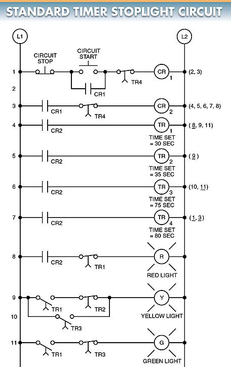
Whenever a standalone timer is used, a simple line diagram represents the circuit. A standard stoplight timing sequence uses four on-delay timers. Take a look at the example in Figure 1. The stoplight circuit’s simplified time values of seconds illustrate the fundamental operation of sequencing three lamps. The lights turn on and off in the following pattern after the circuit start button is pressed and released:
- For 30 seconds, the red light will shine.
- The red light goes out and the yellow one comes on for five seconds.
- After forty seconds, the yellow light goes out and the green one comes on.
- The yellow light comes on for 5 seconds while the green one goes out.
- After 30 seconds, the yellow light goes out and the red one comes on.
- In order to restart the process, Timer 4 must be used.
If you’re using a programmable timer, you’ll need to draw the circuit as a control line diagram. While both the standard line diagram and the controller line diagram serve the same purpose, the former is created manually, while the latter can be generated automatically by a computer.
As the circuit is programmed, the programmable timer’s line diagram is generated on the screen automatically. Refer to Figure 2. Each control circuit line is labeled as a rung in this diagram.
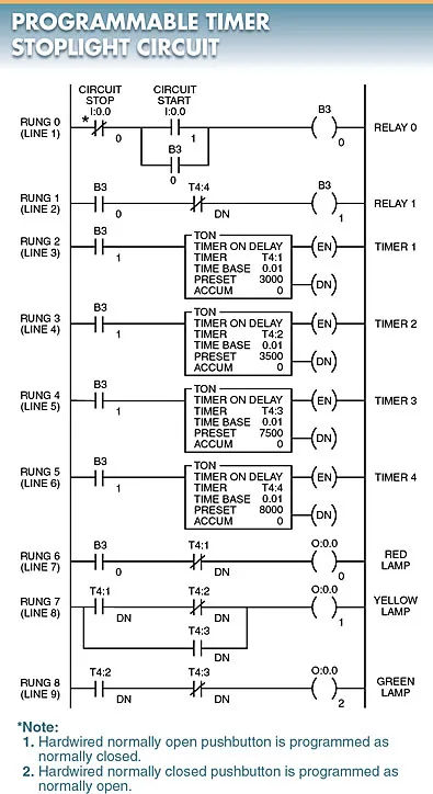
Each rung on the ladder is assigned a number, beginning with 0. Manufacturers’ naming conventions for inputs, outputs, relays, and timers are inconsistent. The following is an example of a common technique for determining who made an item:
- The inputs are addressed as I: 0.0-0 (stop button) and I: 0.0-1 (start button).
- The outputs are addressed as 0:0.0-0 (red lamp), 0:0.0-1 (yellow lamp), and 0:0.0-2 (green lamp).
- The relays are addressed as B3-0 (first relay), and B3-1 (second relay).
- The timers are addressed as T4:1 (timer 1), T4:2 (timer 2), T4:3 (timer 3), and T4:4 (timer 4).
PLC Input and Output Address Identification
I/O devices on a PLC need to be given unique numbers called “addresses” whenever they are given instructions (instruction). The address connects the controller’s data files and processor files with the device’s inputs and outputs.
Despite the fact that each manufacturer gives inputs and outputs unique addresses, there are more commonalities than differences between most manufacturers. Number/letter assignments are commonly used, for instance, in the manufacturing industry’s standard addressing numbering system. Notice in particular Figure 3.
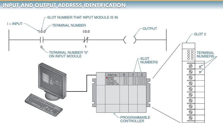
Below is a rundown of how the numbers and letters are assigned:
I = Input (pushbutton, limit switch, etc.)
O = Output (solenoid, lamp, motor starter, etc.)
T = Timer (internal PLC timer)
C = Counter
: = Slot number (physical slot number [1, 2, 3, etc.] of the I/O module)
By way of illustration, I:0/1 specifies an input at terminal 1, and 0:0/4 denotes an output at terminal 0.
PLC Welding Application
Welding is frequently an integral part of the system in the production of discrete parts. Control and automation of welding processes in industrial settings may be achieved with the help of programmable logic controllers. Look at Figure 4.
The programmable logic controller’s versatility in this context allows it to regulate both the welding time and the welding power necessary to achieve the desired result. This controller is set up to only allow the weld to proceed under ideal input and output conditions. Among these variables and prerequisites are:
- completeness and proper assembly of all its constituents.
- the ideal tempo and output for the welding cycle.
- the optimal line speed for the specified use case.
- the integrity of all safeguards and interlocks.
The controller can also be programmed to turn the line on and off automatically based on whether or not supplies are low.
Production efficiency documentation for quality assurance and stock needs can be recorded. Several welders can be managed and interlocked with the help of a programmable controller.
When all the welders at a given station are operating, the total power demand may exceed what is available. Weld quality can suffer if too much power is used. One of the challenges of designing a system with multiple welders is reducing the overall power consumption. This is achieved by limiting the amount of power each welder is receiving at any given time. Power limits can be set in a programmable logic controller. When a welder requests power, the controller can tell if it’s available.
If enough power is applied, welding will occur. If power isn’t currently available, the controller will remember the request and allow the welder to continue the weld cycle the next time it is. Also, the controller can be set up to prioritize a specific welder if need be.
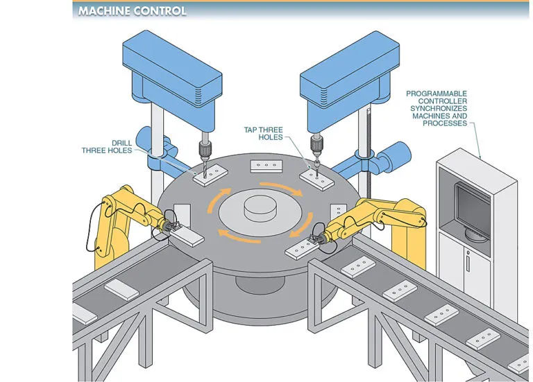
PLC Machine Control Application
When multiple machines are networked together to form an automated system, it is necessary to coordinate their individual controls. View Figure 5.
Another PLC could coordinate the work of all the machines in this setting. If the machines are from different manufacturers, this is a likely result. Each machine could have its own dedicated controller for managing its specific set of functions. It is easier to use a centralized controller to manage and coordinate multiple machines if they were all built or purchased from the same company.
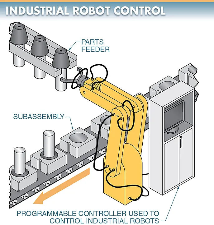
PLC Industrial Robot Control Application
To operate an industrial robot, programmable logic controllers are the best possible devices. Notice in particular Figure 6. Everything from rotation and grasping to withdrawal and extension and lifting can be managed by a programmable logic controller. Since most robots are used in an industrial setting, a controller is highly recommended.
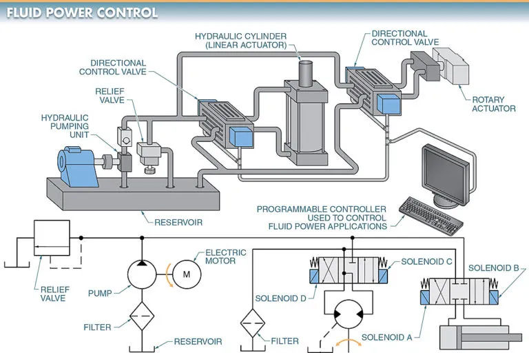
PLC Fluid Power Control Application
When an automated application requires a linear motion, fluid power cylinders are typically the device of choice.
Most plants already have access to compressed air, making pneumatic cylinders a popular choice. Most applications involving robot grippers, drives, positioning cylinders, and machine loading/unloading/tool-working can benefit from pneumatics.
When a manufacturing process calls for very strong forces, hydraulic cylinders are the tool of choice. Components are often punched, bent, formed, and moved using hydraulic systems with pressures of several thousand psi.
In an industrial fluid power circuit, PLCs can be used to regulate both linear and rotary actuators. Check out the 7th figure. The four solenoids in this system are controlled by the programmable logic controller’s output module. Each solenoid controls a different action: solenoid A pulls the cylinder in, solenoid B pushes it out, solenoid C rotates the rotary actuator forward, and solenoid D rotates it backward.
The controller is what turns the power on and off to the solenoids. Actuators are directed by solenoids that operate directional control valves.
PLC Industrial Drive Control Application
Most motors have a fixed speed and run directly off the power grid. Motors need to be able to change their speeds as systems become more automated. To regulate the rpm of AC and DC motors, speed controllers are available. Usually, these controllers are adjusted manually to the desired speed, but many of them also feature automatic control of the set speed. In some cases, an AC drive can be managed by a PLC. In this case, please refer to Figure 8.
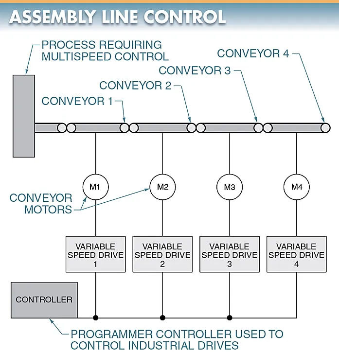
When connected to a PLC with a BCD output module, the drives are able to read and respond to frequency and direction commands in BCD.
PLC in Pulp and Paper Industries
Programmable logic controllers are used in the pulp and paper industries for process control and fault detection. Look at Figure 9.
The machinery used in the pulp and paper industry can take up a lot of room. Since most control logic in the pulp and paper industry consists of start/stop, time delay, count sequential, and interlock operations, a programmable logic controller (PLC) is well-suited to this task.
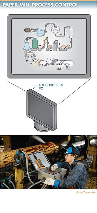
When multiplexed, a PLC’s inputs and outputs can send multiple signals over a single set of wires.
Logs, pulpwood, or chipped wood are just some of the raw materials that are brought into a paper mill before it begins the process of being sized, stored, and shipped out to customers. A substantial conveyor system equipped with diverter gates, overtravel switches, speed controls, and interlocking is integral to this process.
It only takes one malfunctioning component to bring the whole thing to a halt. The system’s expansive coverage can make troubleshooting efforts tedious. A programmable logic controller with fault diagnostics can examine the system, sound an alarm, and print out detailed information about the nature of the problem as well as potential fixes.
PLC in Batch Process Control Systems
Batch processing combines closed-loop, continuous regulation with sequential, step-by-step processing. Controlling a batch process is essentially the same as controlling a system, given that both are composed of many interconnected parts. Each step and component of the process can be managed by its own PLC, with additional controllers and computers providing overall oversight.
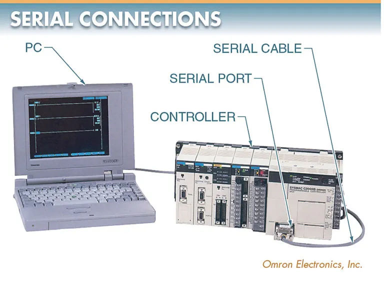
An operator interface is typically utilized in a batch process control system for the purpose of instrumentation or other monitoring functions. The system is enhanced with a user interface for its operators. An HMI (Human Machine Interface) or instrumentation and process control station (IPC) could serve as this interface.
A computer’s serial port can be used for system monitoring and programming, improving the system’s interfacing and monitoring capabilities. This means that at each stage of the process, the local programmable logic controllers directly control the solenoids, motor starters, and heating elements, under the watchful eye of the host computer L1. As shown in Figure 10.