An ohmmeter is defined as a device used to determine the resistance of a given circuit.
The meter movement used in the voltmeter and ammeter can also be used in the ohmmeter. Modifying the ohmmeter to include a voltage source and a tunable resistor.
Series Type Ohmmeter
In Figure 1 we see an ohmmeter of the series type.
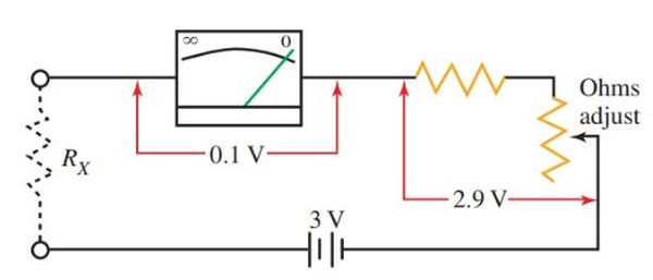
A three volt battery serves as the power source for the ohmmeter. The case of the meter also functions as the battery compartment. Full-scale meter deflection requires more than 0.001 amps, but the meter’s movement can only handle 0.1 volts. Thus, the voltage applied to the meter coil is decreased by connecting a multiplier resistor in series with it.
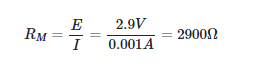
Together, the resistance of the meter coil and the multiplier resistor (both 2900 ohms) produce a total of 3000 ohms. In order to adjust the overall resistance, a variable resistor is used as part of this resistance.
- The ohmmeter needs to be calibrated (adjusted for zero resistance) to ensure the most accurate reading possible, as small changes in the total resistance of the circuit, such as those caused by temperature changes or weak batteries, can throw off the reading.
- There is typically a “Zero Adjust” or omega (Ω) symbol near the knob that is used to set the zero position of the pointing needle.
- First, connect the ohmmeter’s test leads in a “short” configuration. Across the meter, this results in zero resistance. Just turn the ohms knob until the zero indicator appears.
- The needle on the scale should move from its starting position on the left to the zero resistance mark on the right. The battery may be dead or extremely weak if the needle does not move.
- By connecting the unknown resistance to the ohmmeter’s test leads after it has been calibrated to read zero ohms when the leads are shorted, a reading of the resistance can be obtained.
Caution:
Before connecting an ohmmeter to any electrical circuit to read an unknown value, be sure that the circuit is not energized.
An energized circuit will damage the meter and can be harmful to you. The electrical energy in a circuit is not needed to operate the meter movement coil as it is when using a voltmeter or an ammeter.
The batteries inside the case provide the source of power for the ohmmeter. Connecting the ohmmeter to an energized circuit will apply the circuit voltage directly to the coil and battery, which can result in damage to the meter and possible harm to you.
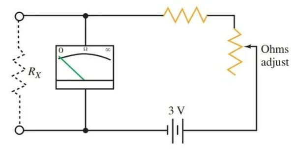
Type Shunt Ohmmeter
As shown in Figure 2, a shunt ohmmeter is wired in. The circuit shown here shuns (connects in parallel) the unknown resistance RX across the meter. When RX is small, the meter reads a smaller current. When RX is high, the meter current reads even higher.
Like an ammeter or voltmeter, an ohmmeter’s indicating needle will sway from right to left when connected in the shunt position. On the left, there’s no opposition at all. Left to right, the numbers get bigger.
Ohmmeter Scales
The ohms scale, a nonlinear scale, is used to indicate the resistance value. The markings on a nonlinear scale aren’t uniformly spaced.
As the needle moves from zero resistance to infinite resistance, the nonlinear scale factor grows. Typical ohmmeter readings are shown in Figure 3’s accompanying scale.
Zero is on the positive side of the scale. Infinity (∞) is located on the left. When an ohmmeter displays “infinity,” it means the resistance value is infinitely high.
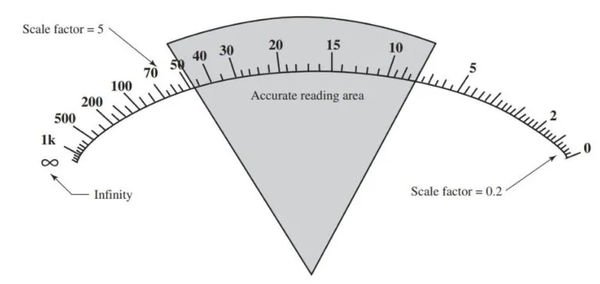
Figure 3. Ohmmeter readings are displayed on a nonlinear scale. Along the range of the scale, the value of the scale factor shifts. The middle third of the scale (where it is shaded) provides the most reliable readings.
Take note of the variation in scale factor across the ohmmeter’s range. To the right, the tiny ticks between 0 and 2 stand for 0.2 ohms. The small marks to the left of the 50 and 70 ohm marks each denote 5 ohms.
Changing the range selector switch until the reading is in the middle third of the scale is recommended for taking accurate readings of resistance values that are unknown.
The selector switch on an ohmmeter allows you to quickly and easily switch between several different ranges. R values in the range of 10 to 100, 1000 to 10,000 are common. If you see these markings, you need to multiply the ohm reading by 10, 100, 1,000, or 10,000.