The three fundamental components of a series RLC circuit share the same current because they are connected in series. There are three distinct kinds of loads that can be used in this formulation.
In the absence of any of the components, the corresponding value for that element can be set to zero or the associated term can be removed from the formulas (typically the inductor or the capacitor, not the resistor).
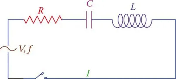
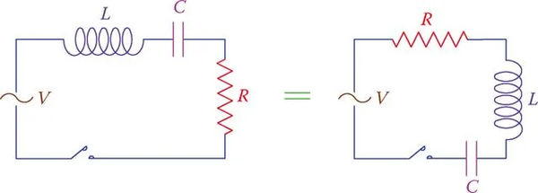
You can see an example of a series RLC circuit in Figure 1. Keep in mind that it makes no difference which of the three components is displayed first. This means that the two circuits in Figure 2 are interchangeable.
In order to solve the circuit at hand, we must apply what we have learned thus far about the relationship between applied voltage, current, and power consumption.
If the details of the loads and the applied voltage are known, the simplest question involving a series RLC circuit is determining the current in the circuit.
Figure 1 shows a simple circuit with three elements: V (applied voltage), I (common current for all three elements), f (frequency), and R (resistance), L (inductance), and C (capacitance).
There are three parts to this circuit, and the applied voltage is shared among them. In this context, VR, VL, and VC represent the voltages across R, L, and C, respectively. Remember that the rules we learned about the connection between current and voltage hold true across the board for each of these voltages. What I mean is,
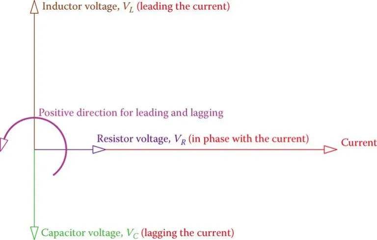
The voltage across the resistor is in phase with the current, the voltage across the capacitor is lagging the current by 90° and the voltage across the inductor leading the current by 90°.
We’ll give it a shot at displaying these variables as vectors now. Considering that all three components draw the same amount of current, I, the current in the circuit, is the best candidate for representing the vectors.
The correct orientation of these vectors is depicted in Figure 3, regardless of their numerical values (since we do not have any number values given yet). One must keep in mind that while the scale for current and voltage can be different, the scale for all identical values (voltages in this case) must be the same.
Figure 3 shows that the voltage across R is in phase with the current, the voltage across L leads the current, and the voltage across C lags the current. Because of this, we can’t use algebraic addition to combine R, XC, and XL. The value Z is the vector addition of these three numbers. Z can be calculated once their values are known.
Since the effects of a capacitor and an inductor are opposite, their corresponding vectors are also opposite, and the sum of these vectors is always less than the larger value (XC – XL or XL – XC).
The two scenarios, depicted in Figure 4, are those in which XC is greater than XL and in which it is smaller. When comparing two numbers, if they are very close to one another, the value of Z that is calculated is the same for both.
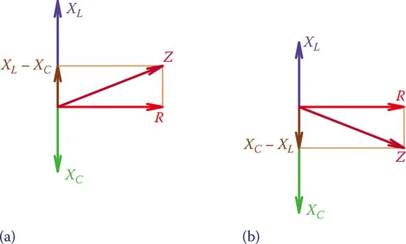
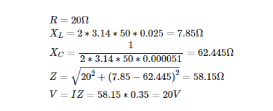
Z, the impedance value, can be expressed as using the Pythagorean Theorem.
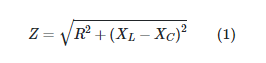
(Note that it does not matter if one enters XL – XC or XC – XL).
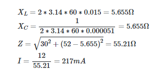
Series RLC Example 1
R = 30 Ω, L = 15 mH, and C = 51 μF make up a series RLC circuit. What is the current in the circuit if the source voltage is 12 V and the frequency is 60 Hz?
Solution
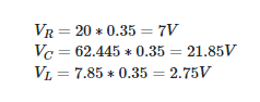
Both Figure 5a and Figure 4a are equivalent. Due to the fact that the current through a series of three identical components is always the same, the values on any of the triangle’s three sides can be multiplied by the current to obtain a similar triangle to the one in Figure 5b. Since RI = VR, ZI = V, etc., the sides of this triangle all stand in for voltages.
In addition, as shown in Figure 5c, the values for the various powers can be reflected in a similar triangle formed by multiplying the sides of this new triangle by I a second time.
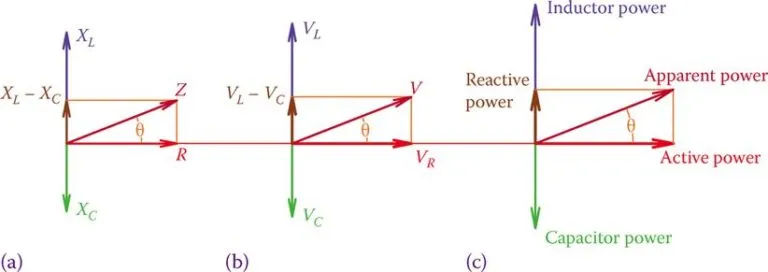
Figure 5 Similar triangles showing powers, voltages, and their relationships in a series RLC circuit. (a) Circuit resistance versus circuit impedance. (b) The voltage across resistance versus the applied voltage. (c) Circuit active power versus apparent power.
The voltages VR, VL, and VC cannot be added algebraically, as shown in Figure 5b. Since vector addition is the only way to combine these voltages because they are out of phase with one another. The connection between virtual reality, virtual reality headsets, and virtual reality headsets with cameras is
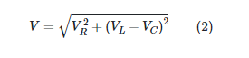
If we replace V with the actual voltage being used. The second term under the radical represents a difference in values between the voltages across the inductor and the capacitor, but this difference is only apparent because the two voltages are 180 degrees out of phase with one another.
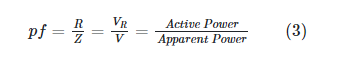
Power Factor in Series RLC Circuits
The power factor for a series RLC circuit can be calculated using one of the relationships shown in Figure 5a-c.
You can tell right away if the circuit is more inductive or capacitive. Consequences of this can be seen in the vector sums XL-XC and VL-VC (see Figure 4).
Series RLC Example 2
The components of an RLC circuit are the 20 Ω resistor, the 51 μF capacitor, and the 25 mH inductor, all connected in series. The circuit current is 350 mA, and the applied voltage is 50 V if the frequency of the source is 50 Hz.
Solution
Each of the three components in a series RLC circuit experiences a voltage that is opposite to the other two.
Series RLC Example 3
When 12 V is applied to the circuit in Example 2, what is the voltage across the capacitor?
Solution
The voltage used in the second example was 20 V. This voltage is split between three parts as shown below:
Since nothing has changed in the circuit, the current will be 0.6 times smaller when the applied voltage is 12 V (i.e., 0.6 times less than the previous case). Since then, 0.6 has been subtracted from all voltages. In this case, the voltage across the capacitor is
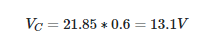
You can now see that it is not always necessary to recalculate everything from scratch. Keep in mind that the 12 V applied voltage is less than the voltage across the capacitor. We don’t anticipate all of the voltages to be lower than the applied voltage, but it’s always possible.
Series RLC Example 4
What is the phase angle between the voltage and the current in the circuit of Example 2?
Solution
The solution can be derived by solving any of the relationships in Equation 3 for the power factor. The optimal choices for R and Z can be found easily.
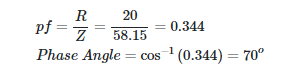
Just knowing that the phase angle is 70 degrees isn’t enough; we also need to specify whether or not the circuit is in a leading or lagging position (i.e., if the current leads the voltage or it lags the voltage). The values of XC and XL provide useful indicators of this. The current is ahead of the voltage if XC > XL, and behind it if XC XL.
Series RLC Example 5
The voltage drop across the series RLC circuit is 48 V, with VR at 15 V and VL at 22 V. Where does the capacitor’s voltage stand?
Solution
Formula 2 suggests that
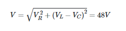
Because VR = 15 V, (VL−VC)2 is determined as (directly from Equation 2)
(VL−VC)2 = V2 – VR2 = 482 −152 = 2079 = 45.62
Since there are two possible outcomes, care must be taken when calculating (VL – VC). In addition, this reflects the fact that when you square (VL – VC) or (VC – VL), you get the same answer either way. Thus,
± ( VL − VC ) = 45.6 V
There is only one valid solution when VL = 22 V. (The alternative value is negative, which is not valid.) So, VC is worth what it’s worth because
VC = 67.6 V
The voltage between any two points in a series RLC circuit can be greater than the externally applied voltage.