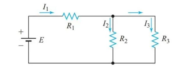
The circuit depicted in Figure 1 is neither a series nor a parallel configuration when taken as a whole. Since R2 and R3 share the same connection between two nodes in the circuit, their voltage drops must be identical. Thus, we can determine a single equivalent resistance for these two resistors because they are connected in parallel.
The simplified circuit of Figure 2 is equivalent to the original circuit of Figure 1 when measured from the terminals of the voltage source. Figure 2 shows a series circuit where R1 is connected to the equivalent parallel resistance of R2 and R3. Therefore, the circuit in Figure 2 can be solved as a straightforward series circuit.
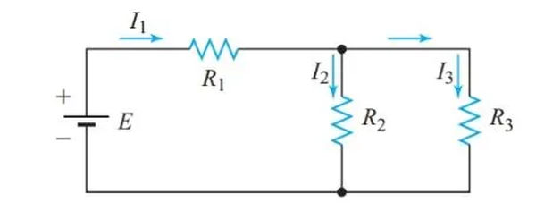
R2 and R3 are in series because they both receive the same amount of current in the circuit depicted in Figure 3(a). As depicted in Figure 3, we can swap them out for a resistor of the same value (b). The simplified circuit shown in Figure 3(b) can now be solved as a straightforward parallel circuit.

Series-Parallel Circuit Definition
A series-parallel circuit is one in which some branches exhibit characteristics typical of simple series circuits, while other branches exhibit characteristics typical of simple parallel circuits.
Series-Parallel Circuit Solution using Equivalent-Circuit Method
Series-parallel circuits can be solved by substituting equivalent resistances for various nodes in the circuit until the system is reduced to a series circuit or a parallel circuit, respectively.
Example 1
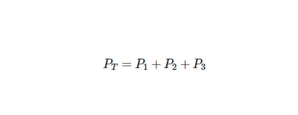
Determine the resistance values, current, and power consumption of each resistor in Figure 4’s circuit diagram.
Solution
- Step 1
Create a labeled schematic diagram of this circuit.

- Step 2
Since R2 and R3 are in parallel,

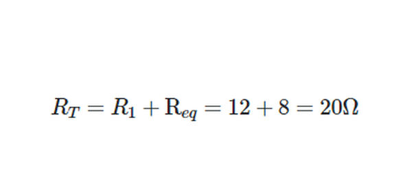
The total resistance of the circuit is
- Step 3
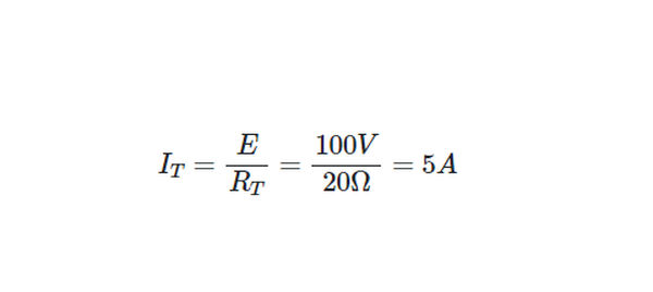
From Ohm’s law,
- Step 4
Since R1 is in series with the source,

- Step 5
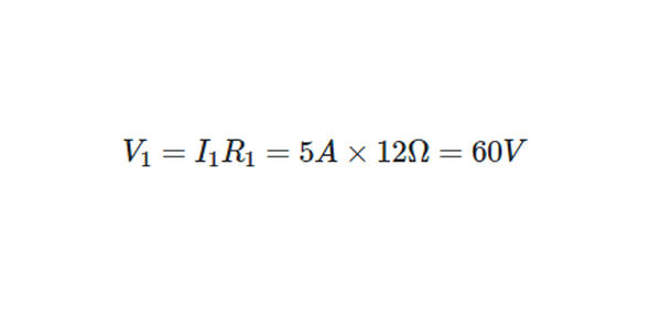
Applying Ohm’s law to R1,
- Step 6
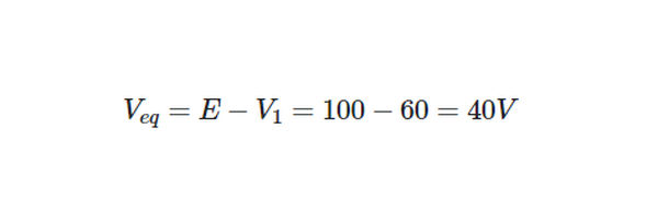
From Kirchhoff’s voltage law,
Returning now to the original circuit,
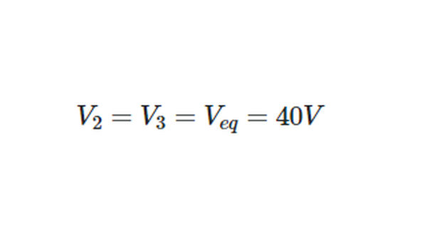
- Step 7
Applying Ohm’s law to R2 and R3,
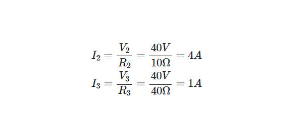
To verify our calculations, we can check that the currents we calculated satisfy Kirchhoff’s current law for this circuit:
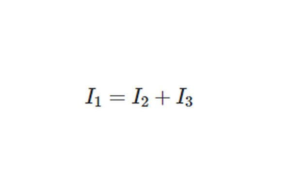
- Step 8
Since,

So,
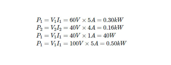
We can verify our calculations by checking that:
Voltage-Divider Principle
Kirchhoff’s voltage law for the series circuit depicted in Figure 5 is E = V1 + V2 + V3. Consequently, the total voltage applied is split between the three resistors. Six different configurations of terminals A, B, C, and D allow us to use a voltmeter, as shown in Figure 5. Because of this, a voltage divider is produced by connecting R1, R2, and R3 in series.
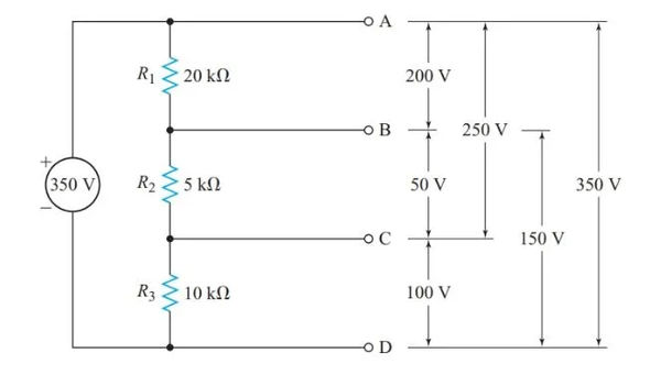
Calculating RT, then I using Ohm’s law, and finally the voltage drop across each resistance using V1 = IR1, V2 = IR2, etc., would give us the six voltages shown in Figure 5. Each voltage, however, can be determined in a single procedure. The voltage-divider principle refers to a characteristic of series circuits:
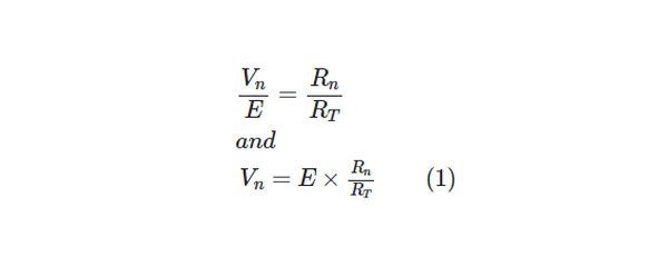
In a series circuit, the ratio between any two voltage drops equals the ratio of the two resistances across which these voltage drops occur.
Hence, for any resistor Rn in a voltage divider,
Example 2
What is the voltage between terminals B and D in the circuit of Figure 5?
Solution
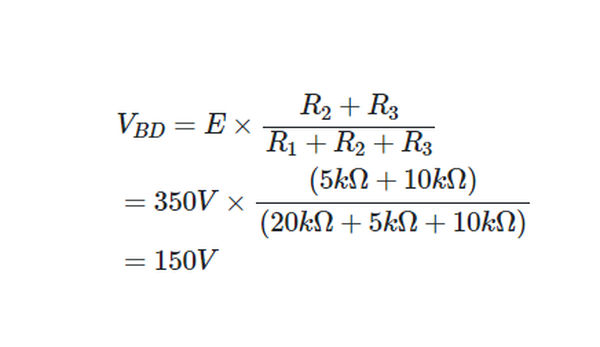
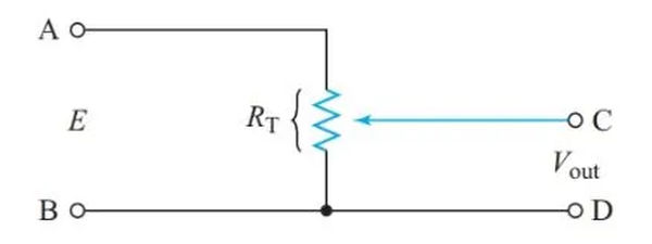
Figure 6 depicts the output of a voltage divider in which a variable resistor is used as a terminal.
Voltage Dividers
In order to reduce the cost, size, and weight of equipment, voltage dividers are commonly used in power supplies for electronic circuits. This allows a single voltage source to supply all of the different voltages required by the equipment.
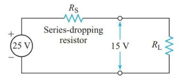
The easiest way to achieve the necessary voltage drop across a specific circuit element is with the series-dropping resistor shown in Figure 7.
Example 3
A 15 V supply and a 20 mA current are needed to power a small section of an electronic circuit. What value of series-dropping resistor is needed if the supply terminal voltage is 25 V?
Solution
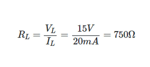
Ohm’s law allows us to use a resistor to symbolize this load circuit, as shown in Figure 7.
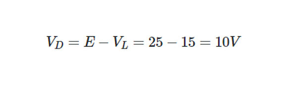
From Kirchhoff’s voltage law, the voltage drop across the series- dropping resistor must be
Since the dropping resistor and the load are in series,
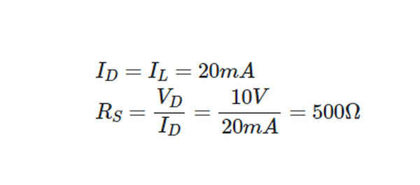
To complete the design, we find the minimum power rating for RS:
P=VI=10V×20mA=0.20W
Since it operates at a cooler temperature, a 0.5-W resistor is preferable over a 0.25-W one, which increases its reliability.
The only draw on the power source is the current through the load, which is why a simple series-dropping resistor is preferable. However, this circuit has the drawback that the voltage supplied to the load and the voltage drop across the series-dropping resistor are both affected by changes in load resistance.
When a transistor is used as the load in a circuit, RL can skyrocket. In this situation, the load voltage is close to the full applied voltage, which could be dangerously high for the transistor because the voltage drop across the series-dropping resistor is nearly zero.
In order to avoid this kind of damage, some voltage-divider designs incorporate a bleeder resistor in parallel with the load, as shown in Figure 8. The series-dropping resistor is designed to always have a sizeable voltage drop across it, and the bleeder resistor guarantees that this current will always flow through it. Since this is the case, the voltage across the load cannot exceed the supply voltage.
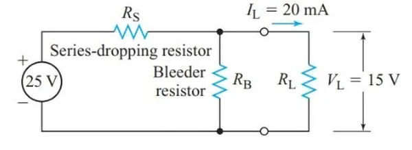
A bleeder current equal to 10–25% of the total current drawn from the source is typically used to protect electronic equipment’s power supplies from overvoltage spikes caused by increasing load resistance.
If the bleeder current is increased, the load voltage will be less sensitive to changes in the load current. Therefore, better voltage regulation is achieved by drawing more current from the source and generating more heat in the voltage-divider resistors.
When planning voltage dividers for loads made up of a single transistor, voltage regulation is more important than a slight increase in bleeder current.
Since multiple voltages can be drawn from a single power supply, it is helpful to have a standard voltage reference in such circuits.
The chassis or metal frame of the circuit is usually wired in and used as a ground. If the electrical system has a ground wire, the chassis can also be connected to it.
Figure 9’s bottom symbol conveys the message that the vantage point is firmly planted on the ground. As a result, we know that the voltage at point A is 1250 V with respect to ground. As shown in Figure 10, the chassis is wired into the circuit at the middle symbol.
In this circuit, the potential difference between points A and B, with respect to the chassis, is 112.
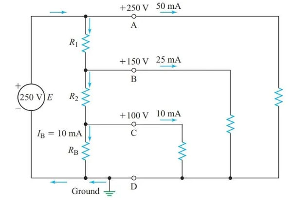
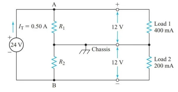
Many electronic circuits employing transistors necessitate either positive or negative voltages with respect to a shared chassis connection. By connecting a tap on a voltage divider to the chassis, as depicted in Figure 10, we can obtain both positive and negative voltages from a single power supply.
Example 5
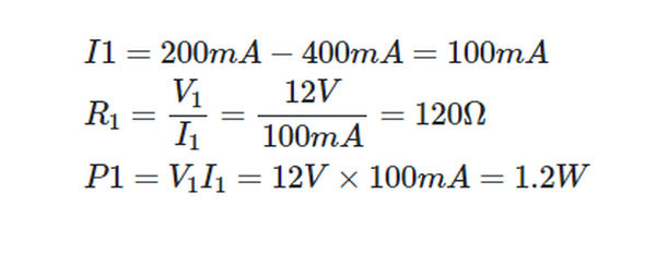
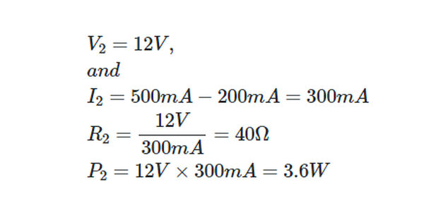
The Figure 10 power supply operates at a terminal voltage of 24 V DC at full load. When the current drains are 400 mA at 112 V and 200 mA at 212 V, respectively, a voltage divider must be designed to provide these voltages with respect to the chassis. A total of 500 mA is drawn from the power supply.
Solution
Because R1 is connected in series with the first load, V1 is able to supply an additional 12 volts. The current version of Kirchhoff’s law, applied to junction A,
Similarly,
Current-Divider Principle
The principle of the current divider can be explained as:
In a parallel circuit, the ratio between any two branch currents equals the ratio of the two conductance through which these currents flow.
Since the voltage is common for resistors in parallel,

And

Substituting Gn = 1/Rn, and GT = 1/Req in Equation 2 gives

Hence, we can restate the current-divider principle:
In a parallel circuit, the ratio between any two branch currents is the inverse of the ratio of the branch resistances.
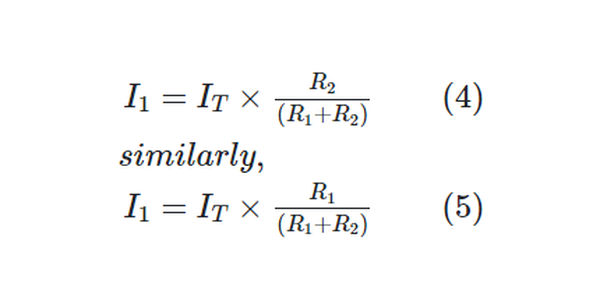
For two resistors in parallel,
Example 6
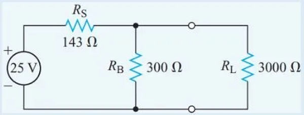
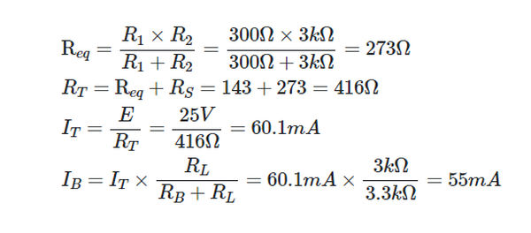
Figure 11 shows a voltage divider with a load resistance of 3.0 kΩ; calculate the bleeder current.
Solution
Since the bleeder resistor and load resistance are connected in parallel, their equivalent resistance is
Cells in Series-Parallel
To increase both voltage and capacity beyond that of the individual cells, a series-parallel battery connection can be used, as shown in Figure 12. In order to prevent internal battery currents from cycling, it is essential that all of the cells be identical. The number of paralleled rows determines the battery’s maximum capacity.
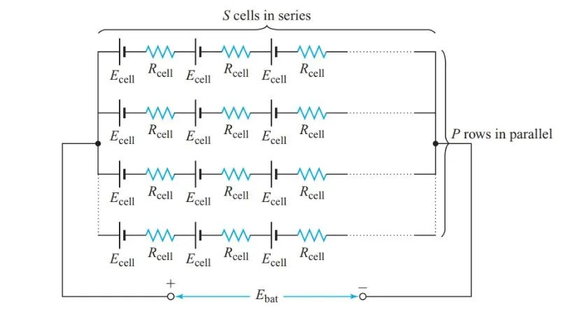
The EMF of a battery with P parallel rows and S series-connected cells is equal to the EMF of a single series-connected row, just as it is for a series-connected battery:

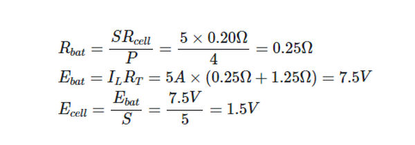
P rows of S identical resistors, each with a resistance of Rcell, connected in series yields an internal resistance of Rcell.

Example 7
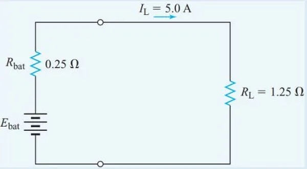
There are twenty cells in total, and they are all connected in series in four rows of five. The internal resistance of each cell is 0.20 V. In Figure 13, we see the battery providing a 5.0 A current to a 1.25 V resistor. Find the cell’s electromotive force (EMF).
Solution
