In response to an applied voltage across its terminals, a capacitor begins charging until its charge is equal to the applied voltage.
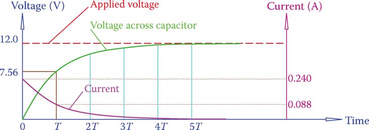
For the duration of the charging process, a current flows through the circuit. As can be seen in Figure 1, this current is caused by the movement of electrons in the wires and not the capacitor. Eventually, this current will die out and reach zero.

It is true that no current flows when the voltage across the capacitor is equal to that of the power source. Figure 2 depicts the resulting current shift in the circuit after the capacitor has been added. When the connection is made for the first time, the current is at its highest.

When a charged capacitor discharges through a circuit, the same justification holds true. The circuit has an ongoing current that lasts until the capacitor is completely discharged.
When the capacitor is first connected to the circuit, the current is at its maximum magnitude and gradually decreases until it is zero. The current variation in a capacitor that is discharging is shown in Figure 3. (A fading exponential curve underlies the fluctuating pattern.)
- Think about the DC circuit shown in Figure 3a, which consists of a capacitor C and two resistors R1 and R2. The capacitor charges and reaches a voltage equal to that of the battery when the switch is turned on and the resistors are powered.
- The charge is depicted as 1 in Figure 3b, which represents the full voltage of the battery. Let’s pretend for a moment that the light has been turned off. The capacitor’s discharge cycle has just started at this very moment.
- The capacitor is discharged through the closed loop formed by R1 and R2. Depending on the time constants C, R1, and R2, the voltage across the capacitor smoothly decreases from its initial value to zero.
- As you recall, it takes roughly 5 the time constant for the circuit to stabilize to a new value after a change in voltage, and T in Figure 3b stands in for the time constant.

Capacitor Connected to AC Electricity
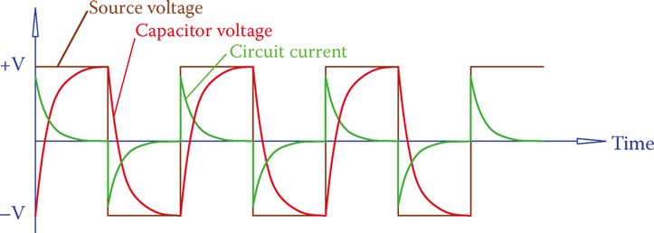
First, let’s assume a square wave AC signal so we can see what happens in an AC circuit with a capacitor. The capacitor begins charging as soon as the connection is made, but either when it is fully charged or just before, depending on the capacitance, the half cycle ends and the polarity flips.
The charged capacitor needs to release its stored energy before it can begin charging in the opposite direction. Flowchart 4 depicts this procedure. While the circuit is on, the capacitor is constantly being charged and discharged, so current is always flowing in the wires connecting the source and the capacitor but is not present within the capacitor itself. As a result, there is a current in the circuit, which can be measured.
By applying Ohm’s law, we can calculate an ohmic value (in ohms) in relation to this current. The second is a current-limiting entity that is not a resistance in the conventional sense. As a result, it does not convert electrical energy into heat.

Capacitive reactance is the current limiting entity that arises from capacitors and is analogous to inductive reactance.
Capacitance, also known as the reactive effect of a capacitor when powered by alternating current (AC), is measured in ohms. The current in a circuit with a capacitor is determined by its capacitive reactance.

- Two scenarios for the current in a circuit with a square wave power source and a capacitor are depicted in Figure 5.
- Contrast Figure 5a, in which the capacitor is fully charged before beginning to discharge, with Figure 5b, in which the capacitor does not have enough time to charge during a half cycle.
- Halfway through the cycle, the current in Figure 5a goes to zero, but in Figure 5b, it’s not zero. Due to the shorter duration of zero value current, the average magnitude of the current in Figure 5b is larger than the current in Figure 5a.
- The capacitor’s capacitance accounts for the disparity in current measurement. As the capacitance increases, the current also grows.
- The frequency effect is also shown in Figure 5. A capacitor has less time to fully charge and discharge as the frequency increases. As a result, the average current is higher since there are no or fewer completely dead-current intervals.
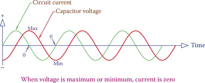
- Figure 5 also demonstrates that when the applied voltage is zero, the maximum current (peak value of current) occurs (the voltage changes sign; it passes through zero). Since the transition from charge to discharge (and this is when the current has its maximum absolute value) begins at the time the voltage changes sign, it is easier to see this for a sinusoidal signal, as shown in Figure 6.
In addition, the maximum (minimum) value of the circuit current for a pure capacitor connected to an alternating current (AC) source (sinusoidal waveform) occurs 90 degrees before the maximum value of the applied voltage (minimum). See Figure 6 to see how this contrasts with the behavior of an inductor.

Current in AC Circuits Containing Capacitor
Figure 5 shows that the magnitude of the current in an AC circuit is directly affected by the line frequency and the capacitance of a capacitor.
It takes longer to charge (or discharge) a larger capacitor because of its higher capacitance, while a smaller capacitor charges (or discharges) more quickly (or discharge). Since current does drop to zero after charging, a longer charging and discharging cycle entails a higher current.
A higher frequency implies smaller cycle time and, thus, less available time for charging and discharging.
If there is less time, the current cannot decrease to zero and more of it will be flowing (higher current). In a circuit with a capacitor, the current is proportional to the capacitance of the capacitor and the frequency of the power source.
Capacitive reactance, like inductive reactance, demonstrates the effect of a capacitor in an alternating current circuit.
In order to calculate the capacitor’s capacitive reactance,

to be expressed as a value in ohms. With respect to Equation 1, f is the line frequency in hertz and C is the capacitance in farads. That means that XC becomes less important at higher frequencies. When C increases, XC loses value (which implies a higher current). As a result, larger capacitors are resulting in higher currents (at the same frequency), confirming the earlier claims.
When the frequency of an AC source connected to a circuit containing a capacitor increases, the capacitive reactance of the circuit decreases and circuit current increases.
Capacitor Current Calculation Example 1
How much current flows through a circuit containing a 12 V, 60 Hz power supply and a 51 μF capacitor?
Solution
Equation 1 can be used to determine capacitance reactance.

Capacitor Reactance Calcualtion Example 2
If the capacitor from Example 1 were connected to a signal with a frequency of 10,000 Hz, what would its reactance be?
Solution
Changing the frequency in Equation 1 to the new value yields

One fact about capacitors in AC circuits is made clearer by this illustration. At 60 Hz, a capacitor has a reactance of 52Ω, but at 10 KHz, it only has a reactance of 0.3 Ω. With the much higher frequencies used by radio and television, this value is practically zero. As a result, a capacitor can be thought of as an electrical conductor.
A capacitor acts like a solid connection at extremely high frequencies.
Capacitance Calculation Example 3
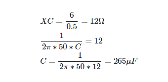
Capacitors draw 500 mA of current from a 6 V, 50 Hz power source. Can you tell me the capacitor’s capacitance?
Solution

Capacitors in Series
Figure 7 depicts a series of capacitors. It’s up to us to identify the lone parallel capacitor that can be used in place of the series arrangement. In contrast to resistors and inductors, series capacitors follow the inverse rule. Capacitors connected in series


If both sides of the above equation are multiplied by 1/2πf, then we get

Which is
Xeq = X1 + X2 + X3 + ⋯ (3)
To calculate the equivalent capacitor for a series of capacitors, Equation 2 must be used; however, the reactance values can be used together to get the correct answer.
Capacitors in Series Example 4
Three capacitors had been connected in series in place of the broken one in an earlier attempt at fixing the circuit. Find the value of the capacitor in the initial circuit if these capacitors are 47, 68, and 100 μF.
Solution
By solving for x in Equation 2, we get

Therefore, the initial capacitor was a 22 μF. (the nearest standard value capacitor).
Capacitors in Parallel
If the desired capacitance value is not available using a single capacitor, it may be necessary to connect multiple capacitors in parallel. Figure 8 depicts a series of capacitors.
An easier rule can be applied to capacitors when they are connected in parallel. Together, their capacitances equal the sum of your calculations. For example,
Ceq = C1 + C2 + C3 + ⋯ (4)
However, they need to be modeled as parallel resistors in order to calculate their equivalent reactance. It follows from Equation 4 when the two sides are multiplied by 2πf. Thus,

Or

Capacitors in Parallel Example 5
The parallel connection of 33 F, 47 F, and 10 μF capacitors. How much does this capacitor cost?

Solution
Simply summing the three numbers together will do the trick.
C = 33 + 47 + 10 = 90 μ F
Keep in mind that 90 μF can also be obtained by paralleling two common 68 F and 22 F capacitors.