The term “pilot device” can refer to either an audible or visual indicator or a physical switch used to regulate power to a procedure. Consider a room’s light switch. This is the pilot device that regulates the power going into the lamp. When turned off, no illumination occurs. The light activates when the switch is turned on by hand. This can be a push button, a selector switch, or the relay’s contacts in a commercial setting. Everywhere you go, you’ll see people using Pilot Devices. They can be used in a variety of settings, including homes, businesses, and factories.
If you could define a good definition pilot device, what would it be? Humans use pilot devices as a means of interacting with a process and of visually verifying its status. Push buttons are frequently used for this purpose, as they allow the user to manually control the machine’s operation. A light illuminates to alert the user that the machine has begun its operation. Piloting devices allow humans to communicate with and receive feedback from process-monitoring machines.
Pilot Devices Types
Pilot devices include everything from push buttons and selector switches to toggle switches, indicator lights, and alarm lights.
Pushbuttons
To manually relay something, a push button is used. When the button is depressed, only one or two contact blocks are switched on or activated by the device. They are triggered by an external signal and then communicate with the MCP to either activate or deactivate a load. These connections may only be temporary, and once broken, the parties go back to being themselves. Maintain contacts are used in some switches. After being switched on, the contact will remain in that position until it is switched off again.
Maintaining a normally closed contact is essential for an emergency stop button. When depressed, it opens the contacts, cutting off power to the process and the control circuit. There is a common practice of color coding push buttons. The universal color for “stop” is red. For start push buttons, the color green is most common, though other colors are possible.
Selector switch
The selector switch is yet another switching device available in the pilot family. Depending on the use, these switches can have two, three, or even more settings. A selector switch’s knob is turned rather than depressed to make selections. While spinning, it makes or breaks contacts on the back via a plunger that is pushed inward.
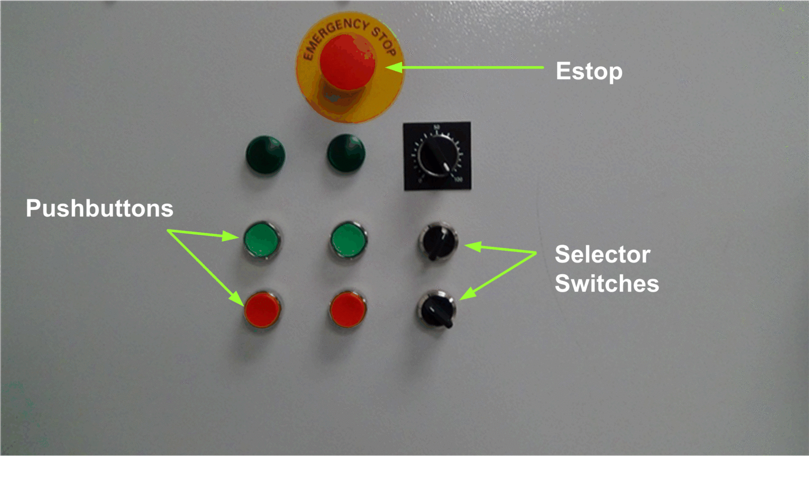
In many situations, changing the circuit logic from automatic to manual or from low to high speed is necessary, and this is where a selector switch comes in handy. Below, pushbuttons, selector switches, and E-Stop are identified.

The aforementioned three switches are not the only ones used as pilot devices. Many variations on the switch exist, including rocker switches, toggle switches, and rotary switches. The basic premise of all of these systems is the same: a user interacts with a device to open or close a contact, allowing data to flow and states to be modified.
Traffic Light
Audio and visual piloting aids are also available. When the light is red, you come to a complete stop; when it turns yellow, you slow down; and when it turns green, you go. All of these are prototypes being tested in limited capacities.
They don’t actually drive the car, but they do provide useful visual feedback for the driver. The same applies to industrial pilot equipment. Indicator lights for when you’re up close and personal, and stack lights for when you need to keep an eye on things from afar, can both be found on the same panel.

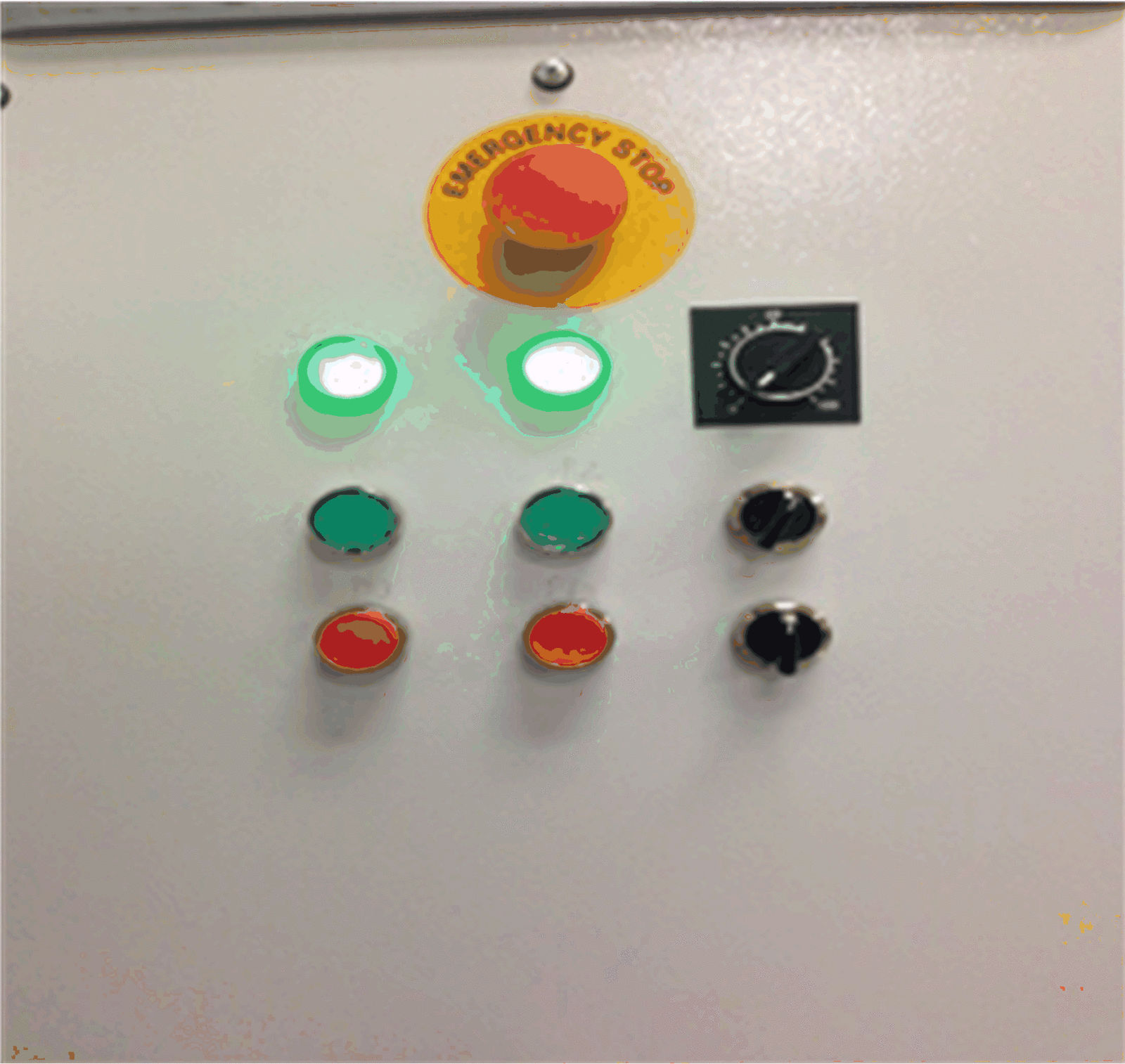
Typically, a single-colored light serves as an indicator. They may be the older incandescent variety or the more modern LED variety. They typically appear on the MCP’s front panel and indicate whether or not a given circuit has been powered on. Some images of the indicator light are provided below.
Stack Lights
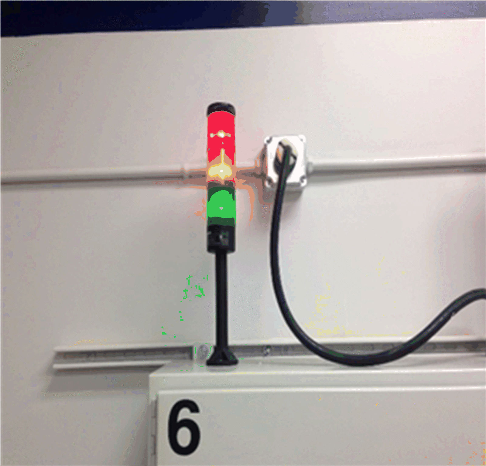
In most cases, stack lights will be installed at a greater height and will be physically larger than standard lights. You should view them from a greater distance, which is why they look this way. Their adaptability to individual needs is what sets them apart. Stack lights can be “stacked” in either a vertical or horizontal orientation. It’s possible to use as few as one stack light or as many as seven, depending on the scenario. Each bulb’s color represents a different step in the procedure.

Three lights are used in the image below. If it turns red, the procedure may have been halted. Its color can be used to denote the status of the process, with green indicating normal operation and yellow signaling the presence of an error that requires attention.