Ceiling fans, air conditioners, washing machines, and refrigerators are just some of the common household appliances that rely on single phase induction motors. Split-phase motors, shaded-pole motors, and capacitor-operated motors are all examples of this category.
An AC (alternating current) motor is an electromechanical device that uses electromagnetism and the varying frequency and voltages produced by the utility company or motor controller to transform electrical energy into mechanical movement.
Given their versatility and low maintenance requirements, AC motors are a major contributor to global electricity consumption. In terms of cost and simplicity, the AC motor dominates the industrial motor market.
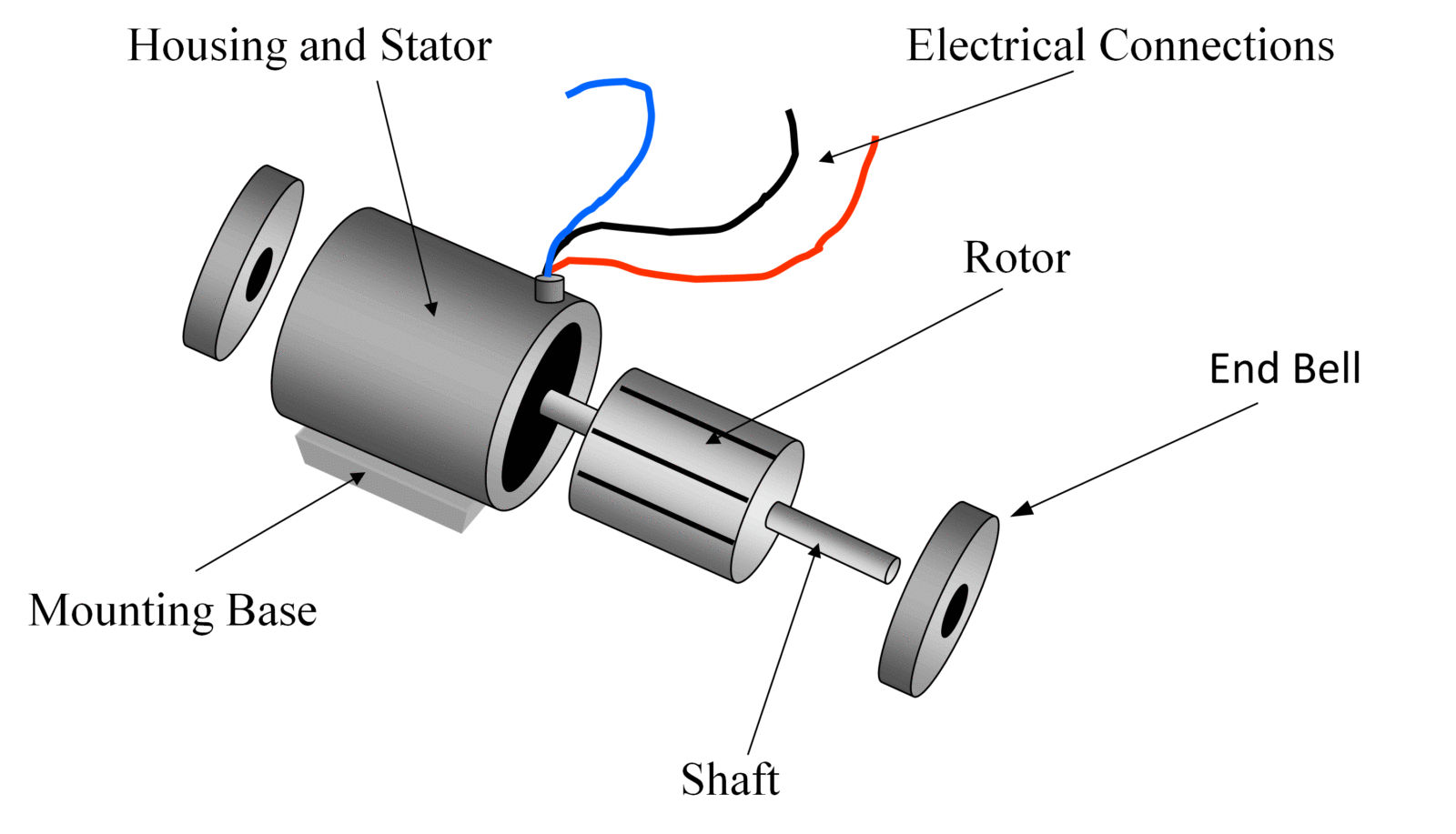
There aren’t many moving parts in an AC motor, but as long as it’s used correctly it can last for decades or even centuries with only occasional servicing. As can be seen in Figure 1, the rotor and stator make up the bulk of an AC motor.
In an AC motor, the rotor spins on bearings housed in the end bells to ensure smooth operation. To facilitate easy movement, bearings are pressed into a set of end bells that are then filled with lubricant.
The laminate sheets of iron that form the stator and around which the windings are wound to generate an electromagnetic rotating field when the coil is energized are the stationary part of the motor.
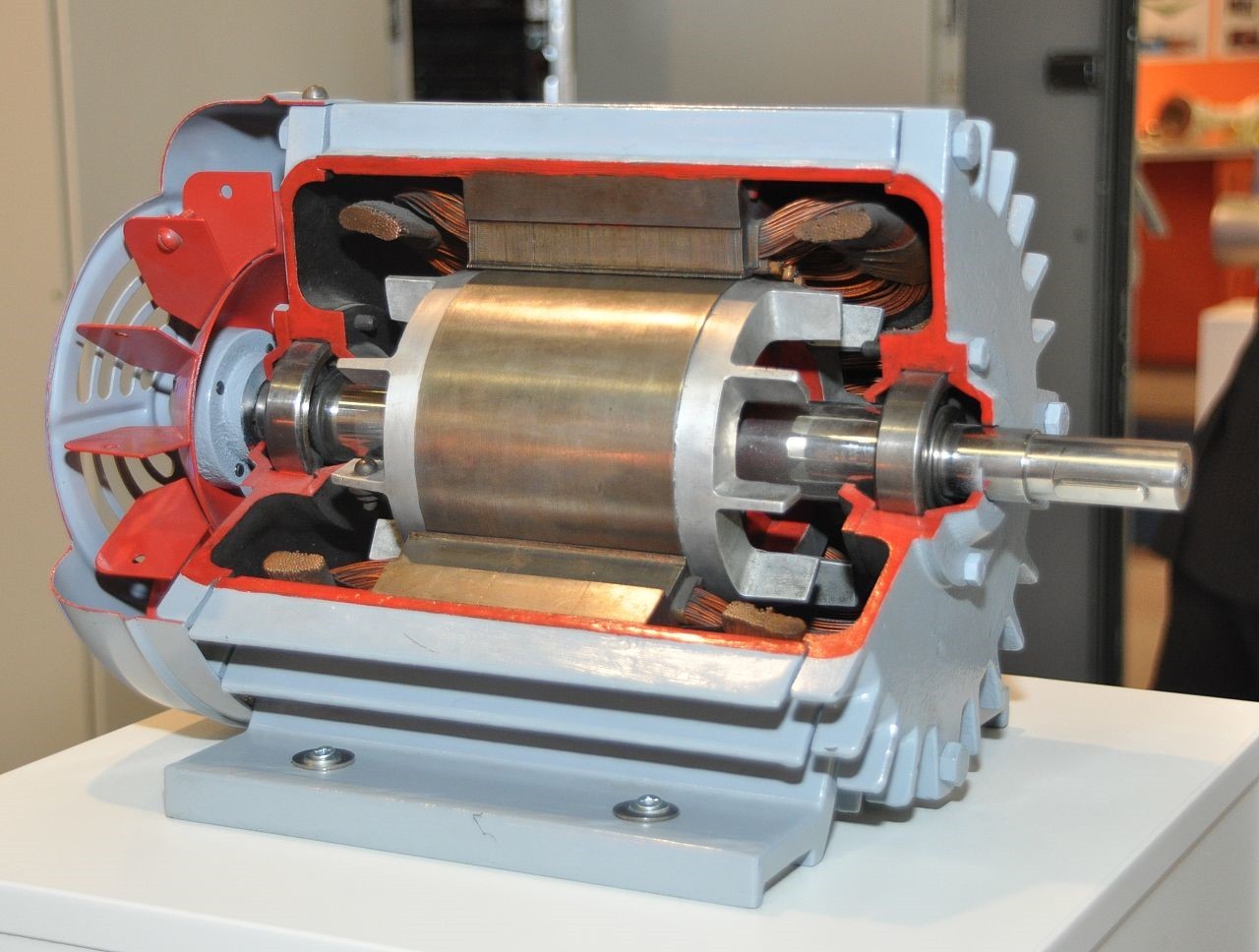
Motors are extremely adaptable electromechanical parts because they can be made in a wide variety of sizes, configurations, and constructions to meet a wide variety of needs. Figure 2 shows that single-phase and three-phase motors account for the vast majority of industrial motors.
Single Phase Induction Motors
An electric motor that only requires one phase of alternating current to run is called a “single phase induction motor.” When it comes to AC motor appliances in a home, a single-phase induction motor is your best bet. Single-phase induction motors can be classified into three distinct varieties: those with a shaded pole, those with a split phase, and those with a capacitor.
Shaded pole Motor
Shaded Pole motors, such as the one depicted in Figure 3, are single-phase induction motors typically used to power the miniature cooling fans housed within computer cases. They’re a type of induction squirrel cage motor used for low-power tasks (typically between 1/20 and 1/6 HP) that wouldn’t benefit from a higher-powered model.
The heaviest load a shaded pole motor can handle is a lightweight, spindle-shaped component with a low density. When a shaded pole motor fails, it is typically recycled and replaced.
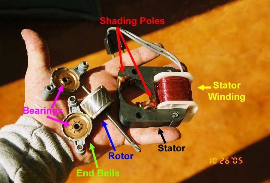
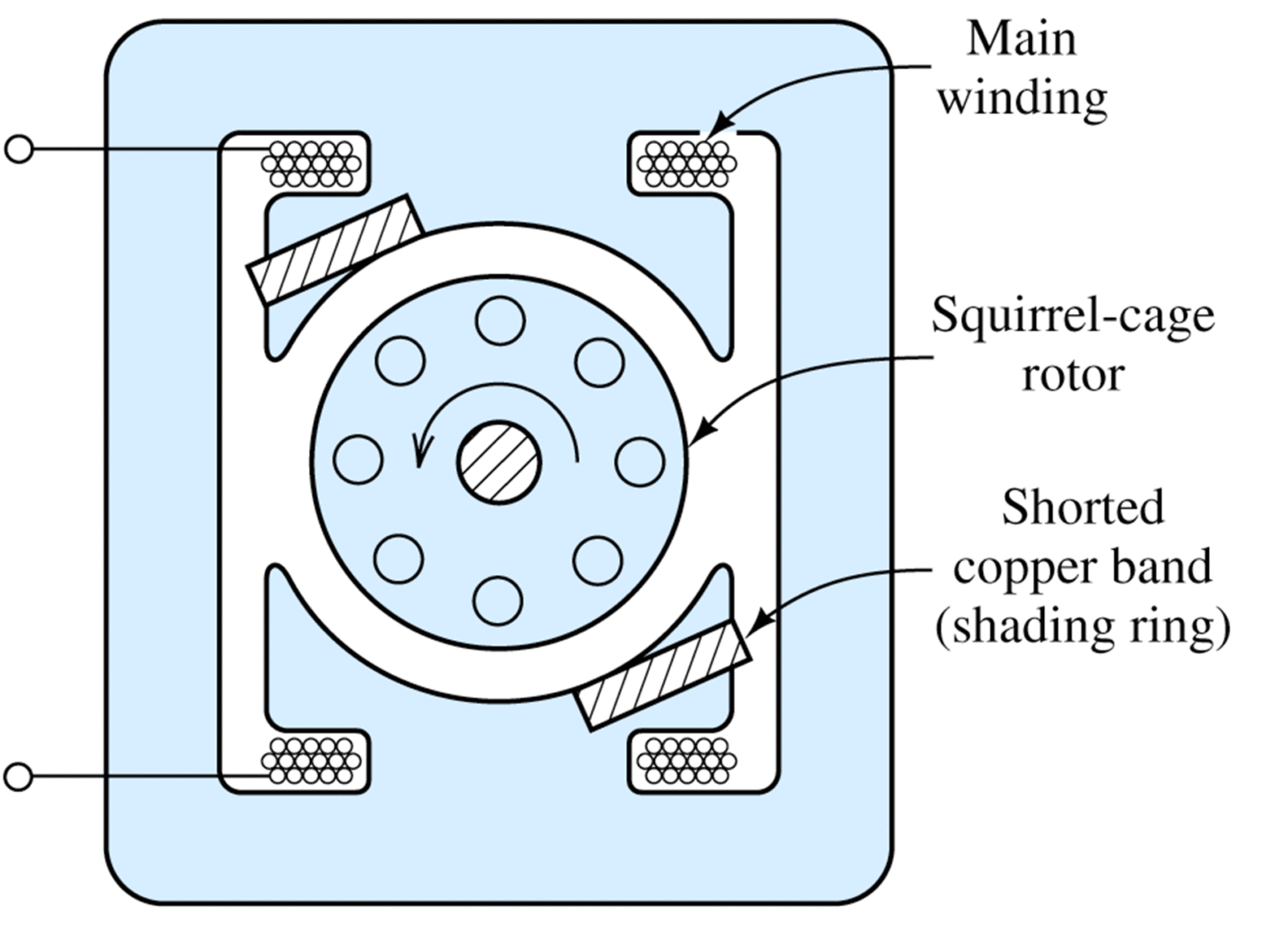
Each of the stator poles has what is called a shade winding installed in its corner, and it can be seen in fig. 4. These windings generate a rotating magnetic field via induced current rather than an external electrical connection.
By delaying the buildup of magnetic flux, the pole structure of the shaded pole motor allows for the development of a rotating magnetic field. A copper conductor winds around the pole in a complete circle, isolating the shady section. Because of the current induced in the copper shield, the increase in magnetic flux in the shaded area is slowed. As the winding current increases, a rotating magnetic field is formed in the area not covered by the shading.
Split Phase Motor
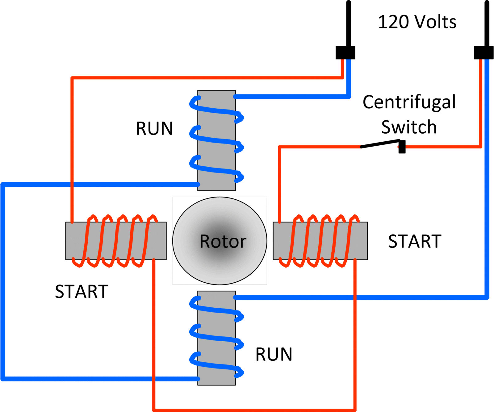
Figure 6 depicts a split phase induction motor, which is a type of single phase induction motor with two windings: a primary run winding and a secondary start winding connected by a centrifugal switch. One-third to one-fifteenth of a horse power is the typical range for split-phase motors.
When compared to shaded pole motors, squirrel cage motors are superior due to their ability to withstand greater loads on the rotor’s shaft.
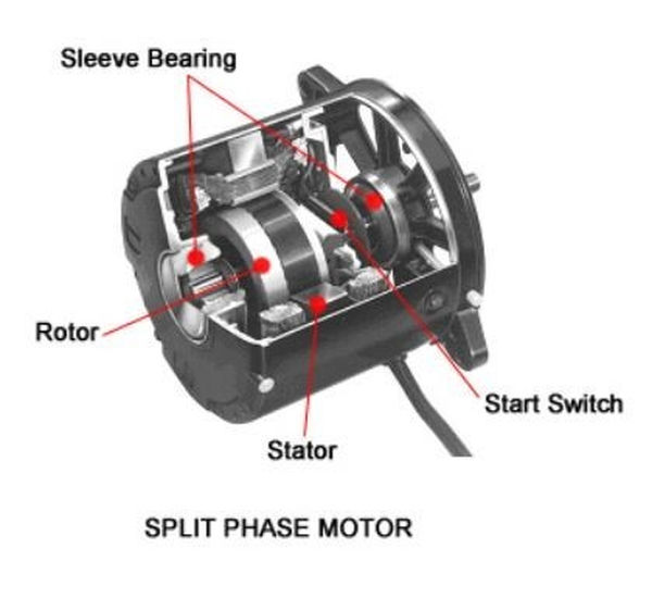
Ceiling fan blades, washing machine tubs, oil furnace blower motors, and small pumps are just some of the many uses for the versatile split phase motor.
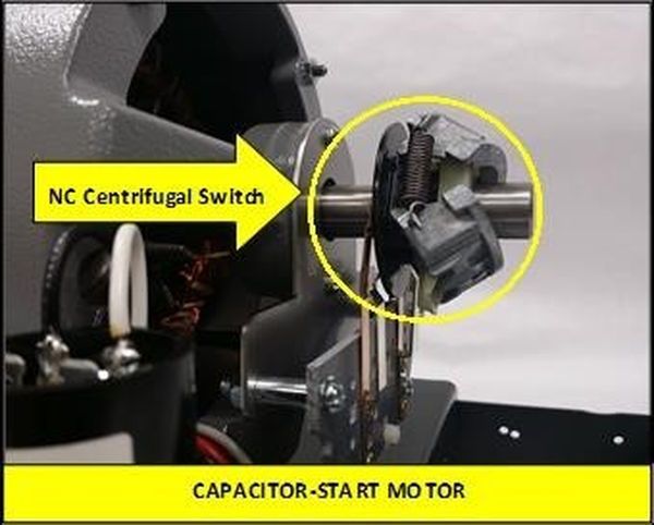
The start winding is connected to the centrifugal switch, which is a normally close control device. The goal of this setup is to disconnect the motor’s start winding once the motor’s speed reaches 75% to 80% of its rated speed. A centrifugal switch is a moving part that occasionally disengages after the motor has stopped spinning, despite the motor’s reputation for dependability.
How Split Phase Motors Operate?
- Parallel connection of the start and run windings is required to initiate rotation in a three-phase induction motor.
- The start winding is cut off when the centrifugal switch opens at 75% of full speed.
- The motor is currently being powered by the run winding as the start winding has been removed from the circuit.
- At 40% full load speed, a centrifugal switch closes to cut power to a split-phase motor. Switching off the engine’s power.
Capacitor Motors
To advance from the single phase induction motor family, single phase capacitor motors were developed. Motors with capacitors have the same start and run winding as split phase motors; the difference is that the capacitor increases the motor’s torque at startup and during operation. In a single-phase system, the capacitor is used to restore voltage when the DAC sine wave is not being generated.
There is only one voltage wave form in an AC single-phase system, and no voltage is generated at two points simultaneously for the full 60 hertz required to generate that voltage. In order to ensure the motor is always receiving a voltage and therefore producing a lot of torque, it is the job of the capacitor to fill this void.
The three types of capacitor motors are capacitor start, capacitor run, and capacitor start and run motors.
Capacitor Start Induction Motor
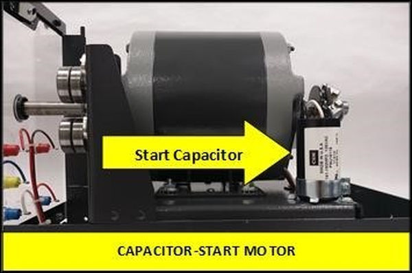
A capacitor is connected in series with the start winding and the centrifugal switch of a capacitor-start induction-run motor, as shown in Figure 7. When set up in this manner, the motor has more than enough power to get going, but the application’s runtime needs are modest. Motor operation is heavily influenced by the inertia of the load during the running time, and problems are typically caused by a faulty capacitor. The motor won’t turn unless the shaft is spun by something else, but once it’s going, it’ll keep going until the power is cut.
Most air conditioners, large blower motors, and condenser fans use capacitor start motors. Sometimes the motor’s capacitor is built right into the motor, and other times it’s located away from the motor in a more convenient location for maintenance.
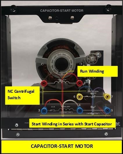
Capacitor Motor Operation
- Consists of a figure-8-like start winding, a run winding, and a centrifugal switch that activates at 60 to 80% of full load speed.
- As can be seen in Figure 9, once the centrifugal switch is opened, the start winding and capacitor are no longer needed.
- To start with a lot of torque, the capacitor is necessary.
Capacitor Run Induction Motor
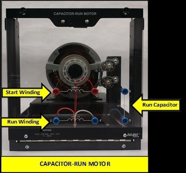
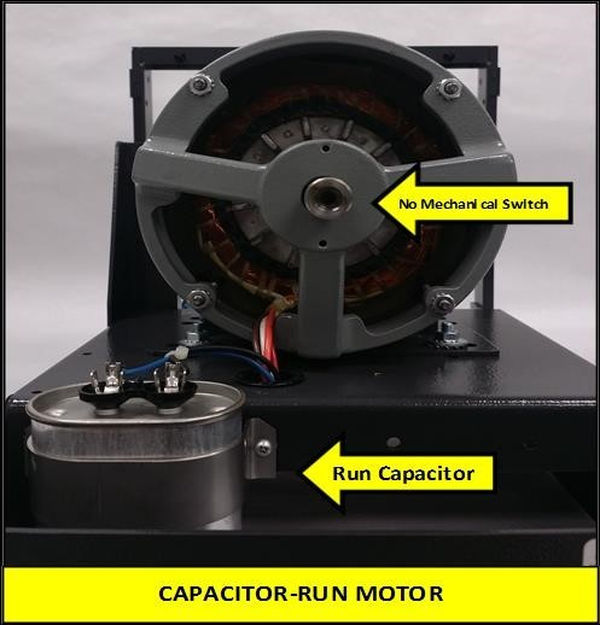
Figures 10 and 11 show capacitor run induction motors, which are similar to capacitor start induction motors except that the start winding and run winding remain connected to the circuit at all times. This type of motor has a low torque requirement for starting but must maintain a steady torque throughout operation. In some cases, the air conditioner’s compressor will use this type of motor. An always-on series connection between the start winding and capacitor ensures reliable operation.
Capacitor Run Operation
- Capacitor is always on, so a smaller one can be used.
- This helps to increase the running torque.
Capacitor Start-Capacitor Run Induction Motor
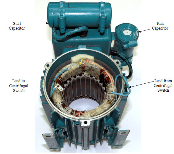
A capacitor is placed in the start winding and the run winding of capacitor start capacitor run induction motors, as shown in figures 12 and 13. (wiring diagram). For heavy-duty tasks like driving large water pumps, this motor type is built to deliver high starting torque as well as stable performance.
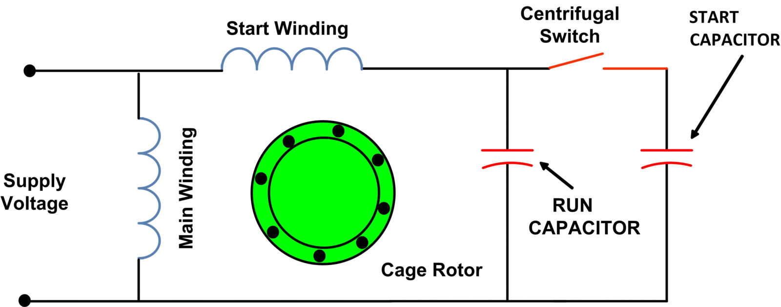
Capacitor Start-Capacitor Run Motor Operation
- include a pair of capacitors
- Both capacitors are wired in series with one of the windings: the start winding for the first one and the run winding for the second.
- They are of different values because the capacitors are different sizes.
- Since there is more capacitance in a capacitor start/run motor, the running torque is greater than the starting torque.
- Initially, a higher value capacitor is used, while a lower value capacitor is used during operation.