Both vertical- and horizontal-axis wind turbines exist, with the former being the more common type (VAWT).
The main components of VAWTs, such as the generator and gearbox, are situated at the base of the turbine, making maintenance and repairs easier. The rotor shaft of a VAWT is typically but not always perpendicular to the direction of the wind.
Without having to be oriented toward the predominant wind direction, VAWT are able to gather airflow from all directions. Bending moments on the blades result in mechanical stress and material fatigue in conventional designs like the Savonius, Darrieus, and Giromill because of significant torque variation during each revolution.
Although VAWT have been the subject of research and deployment in the recent past, HAWT have been the driving force behind the recent commercial success of wind turbines.
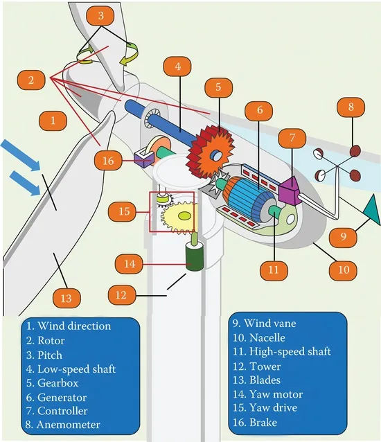
In Figure 1 we see the standard HAWT wind turbine components. Components can be broken down into mechanical, electrical, and control subsets. Here is a breakdown of the primary parts:
- The wind turbine is mounted on a tower. It holds up the wind turbine’s nacelle, rotor, and blades. In the business world, concrete or steel is the material of choice, and the typical height of a wind tower is between 50 and 120 meters.
- In normal operation, with wind speeds between about 3 and 15 meters per second (m/s), the maximum power possible from the wind is captured by the blades, which are physical structures that have been aerodynamically optimized for this purpose. Depending on the output, each blade can be 20 meters or more in length.
- The nacelle houses the wind turbine’s generator, gearbox, and other mechanical components. It shields the turbine’s inner workings from the elements.
- A wind turbine’s rotor is its moving part. It is able to transmit the wind’s energy to the shaft. The wind turbine’s blades are held in place by the rotor hub, which is in turn connected to the gearbox by a low-speed shaft.
- Pitch is the means by which the rotor blades’ angle of attack can be altered. Altering the blades’ angle of attack by rotating them along their longitudinal axis allows the turbine to adapt to prevailing wind conditions.
- There are two distinct varieties of shaft, one designed for low speeds and another for high speeds. Mechanic power is transmitted from the rotor to the gearbox via the low-speed shaft, and from the gearbox to the generator via the high-speed shaft.
- The turbine’s yaw is the part that rotates laterally. Depending on the direction of the wind, it either rotates clockwise or counterclockwise. There are two primary components that make up the yaw: the yaw motor and the yaw drive. When there is a change in the direction of the wind, the yaw drive keeps the rotor pointed in the right direction. To turn the yaw, the motor is engaged.
- The wind turbine’s rotational speed can be slowed down or stopped entirely thanks to the brake, a mechanical component attached to the high-speed shaft.
- A gearbox is a mechanical device that can change the rotational speed of a motor. The wind turbine gearbox regulates the rotational speed of the generator.
- The kinetic energy produced by the rotor is transferred to the generator, which produces electricity. Induction generators (IGs), doubly fed induction generators (DFIGs), and permanent magnet synchronous generators (PMSGs) are the most common types of electrical generators used in wind turbines (PMSGs).
- The wind turbine’s control unit acts as its central processing unit. It constantly checks on the wind turbine’s health and adjusts its pitch and yaw to get the most out of the wind’s energy.
- The velocity of the wind can be determined with the help of a device called an anemometer. In extreme circumstances, knowing how fast the wind is blowing could be crucial for monitoring and safeguarding vital power supplies.
- One sensor used to determine wind direction is the wind vane. Having knowledge of the wind’s direction is crucial for the yaw control system to function.
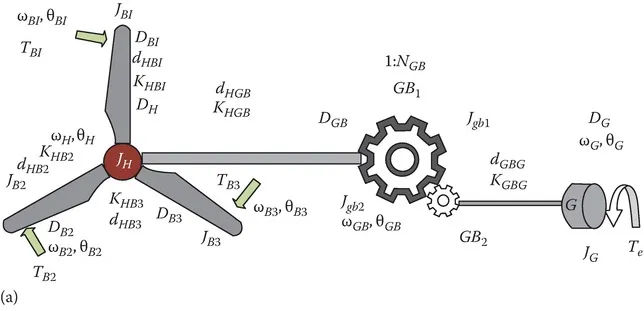
Figure 2a depicts the gearbox of a wind turbine. It depicts a six-mass drivetrain model with six inertial masses, including three rotor blade inertial masses (JB1, JB2, and JB3), a hub inertial mass (JH), and gearbox and generator inertial masses (JGB and JGB, respectively) (JG).
Blade 1, Blade 2, Blade 3, Hub, Gearbox, and Generator Speeds are denoted by θB1, θB2, θB3, θH, θGB, and θG respectively, while Blade 2, Blade 3, Hub, Gearbox, and Generator Speeds are denoted by ωB1, ωB2, ωB3, ωH, ωGB, and ωG. respectively.
The spring constants KHB1, KHB2, KHB3, KHGB, and KGBG characterize the elasticity between adjacent masses, while the damping constants dHB1, dHB2, dHGB, and dGBG characterize the mutual damping between adjacent masses.
Torque losses occur due to mass-specific external damping elements denoted by DB1, DB2, DB3, DH, DGB, and DG.
One generator torque (TE) and three aerodynamic torques (one on each blade) are needed for this model to work (TB1, TB2, TB3).
The turbine’s torque (TWT) is derived from the sum of the torques applied to the blades. It is assumed that the hub and gearbox experience no aerodynamic torque.
Due to the complexity of the six-mass model, a simplified two-mass model with equivalent shaft stiffness K2M is typically used instead (shown in Figure 2b). This model combines the masses of the turbine and gearbox into a single mass.