Three-phase induction machines are multifunctional, able to serve as both generators and motors. However, because the stator must be wired into the three-phase circuit, the rotor’s speed determines whether or not this device operates as a motor or a generator.
In general, if the rotor speed is higher than the synchronous speed, then it behaves as a generator, and if the rotor speed is less than the synchronous speed, it becomes a motor.
The synchronous frequency is based on the line frequency and the number of poles in the stator winding.
When the stator is wired in, the resulting rotating magnetic field spins at a constant rate. This causes the rotor to rotate in the same direction as the magnetic field (hence, a motor), but if mechanical energy is applied to the rotor shaft, it can rotate faster than the magnetic field and act as a generator.
A typical induction machine characteristic curve is depicted in Figure 1. relationships between torque and velocity are involved.
The induction motor and generator operations are each represented by a separate, nearly symmetrical curve. This curve can be displayed in a different way (by swapping the coordinates), or it can be extended from the motor side to display additional characteristics (such as dynamic braking, in which the direction of the developed torque is to the opposite of rotation, thus a braking action), but for our purposes, we are only concerned with the data that can be observed from the curve itself:
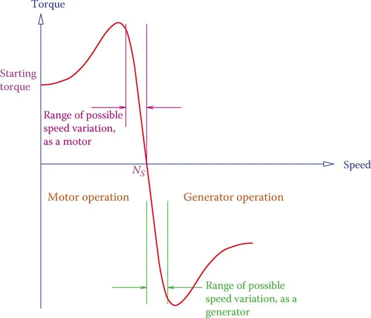
- For the machine to function as a motor, the rotor speed must be less than the synchronous speed (NS), at which point it can transfer torque to the load. When the load is moving at a certain speed, a different set of torque values is calculated.
- Only the nearly linear portion of the curve can be used effectively. Outside of this linear segment, the machine cannot be used as a motor or generator effectively.
- The machine is self-starting because it functions as a motor and has a starting torque (at zero speed).
- When a motor is in its linear (operating) region, the relationship between torque and speed is inverse: as torque increases, speed decreases and vice versa. The motor is incapable of producing any torque at the synchronous speed NS.
- If the generator’s speed is raised within the linear region, the demand for torque will rise proportionally. It’s a self-regulating behavior that keeps a machine from going berserk.
- When the machine is operating at a speed of NS, it generates zero power (since torque is zero and power = torque speed).
Based on what has been said so far, it follows that when operating as a motor, the speed is always lower than the synchronous speed, and when operating as a generator, the speed must always be higher than the synchronous speed.
Some wind turbines’ modes prevented them from using an induction generator. This is a clever decision due to the fact that a variable wind speed can cause the operating point of an induction generator to shift along the linear portion of the generator’s characteristic curve. In this way, a generator can turn faster and generate more power at higher wind speeds without affecting the synchronous speed.
Figure 1 shows a fairly typical curve. Each machine has its own unique resistance in the windings and external circuit, so the shape of the curve can vary from one instance of a WRIM to another.
The ratio of the rotor speed to the slip speed, or the difference between the synchronous speed and the rotor speed, is known as slip.
The percentage of slip is typically less than 3%. That’s determinable from
Slip speed: Difference between the speeds of the rotor and the rotating magnetic field in an AC induction machine.
Slip: The fact that the rotor of an induction machine does not rotate with the same speed as the rotating magnetic field (turning faster in a generator and slower in a motor).
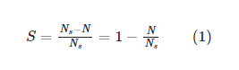
Synchronous speed (NS) equals rotor speed (N). NS < N for a generator, making S negative. As a generator, the frequency of the electricity it injects into the AC line remains constant at NS, regardless of how much larger N is.
The operating point, which is determined by the required load torque, determines the rotor speed N of an induction motor and, by extension, the slip (so, for a motor, if torque is higher, speed is lower). When the prime mover of a generator matches the torque demand on the shaft, the generator is in equilibrium.
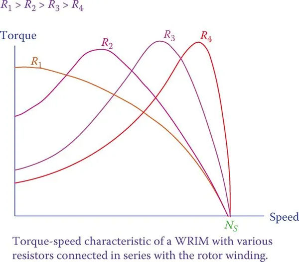
The external resistor R can be adjusted in an induction motor with a wound rotor. This changes the machine’s characteristic curve (both as a generator and as a motor). The result of this modification is shown in Figure 2. (only the motor part is shown). At rest, there is an impact on slip and torque.
External resistance is not present in a squirrel cage machine. The cage’s bars can be made to have any shape (they don’t have to be round) and be placed anywhere (closer to or further from the cage’s center) to achieve the same result (a shift in the characteristic curve). The double-cage machine employs two separate sets of bars.
It takes three wires to properly connect a three-phase induction motor. It is possible to change the rotational direction by switching (any) two connections.