Simple control circuits consist of various wire configurations that represent logical electrical circuits. These permutations work together to allow a machine to carry out a particular job. Electricians need to know the basics of control circuits and be able to sketch and wire them quickly, as these circuits are the building blocks of even the most complex circuits in industry.
Two-wire controls, three-wire controls, manual/automatic controls, sequential controls, stop/start controls, forward/reverse controls, and jogging controls are all examples of the most fundamental control circuits.
Two-Wire Control
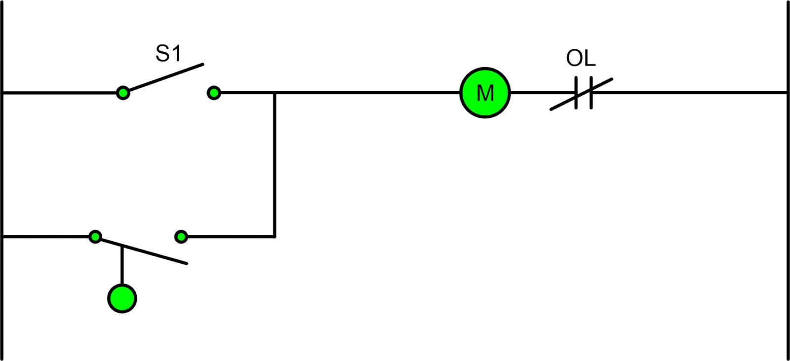
In configuration 1, we see a two-wire control system in which a single set of contacts is used to turn a pilot device on and off.
Most two-wire controls are only rated for low-current operation. Single-phase 240V, 208V, or 480/277-volt circuits can only be controlled by using a single set of contacts, so this type of control system is inadequate for managing high-current loads.

Light switches and motor controls are just two of the many applications for two-wire switches and controls.
The unshown motor or resistive load in configuration 1 is turned on by a switch connected to a motor starter coil. When the switch is closed, power flows to the relay, which in turn energizes the motor’s solenoid and pulls in the armature, allowing the pilot device’s main contacts to supply full line voltage to the load.
A control device that senses a change in pressure or physical location is an automatic two-wire control system, just like a switch is a manual two-wire control system for manually controlling a load.
An automatic control circuit is one in which the state of the control device contact changes automatically in response to an external stimulus.
A load in a circuit that is triggered by an event in a controlled environment automatically constitutes an automatic control system. Switches that automatically respond to changes in the system’s census, such as those for liquid levels, pressure, floats, flows, and so on, are used in such setups. Manufacturing relies heavily on automatic control systems. Numerous control devices are integrated into the control system at various stages of production to ensure accurate motion and timing.
Manual and Automatic Controls
A two-wire control system, also known as a hand-off-auto system, is built so that a load can be operated either manually by keeping power to the coil via a toggle switch, as shown in the diagram below, or automatically by a control device similar to a liquid level switch.
To prevent the load from being turned on or off in the absence of an operator, a float or limit switch is connected in parallel with the toggle switch when the latter is not engaged.

The second configuration’s two-wire circuit works as follows:
- The motor starter will turn on and remain on as long as the single pole switch is toggled closed.
- Leaving the S1 single pole switch open makes the liquid level switch the device that activates the motor starter.
- Because the liquid level switch or the single pole switch could activate the control circuit at any time, the motor starter’s coil would always be energized and the load would remain on unless the entire control circuit lost power.
Tri-Wire Switching
The start/stop circuit requires just three wires and is the simplest form of control circuit. The stop/start circuit’s primary function is to let the low-voltage control circuitry for a motorized load be located in a separate panel.
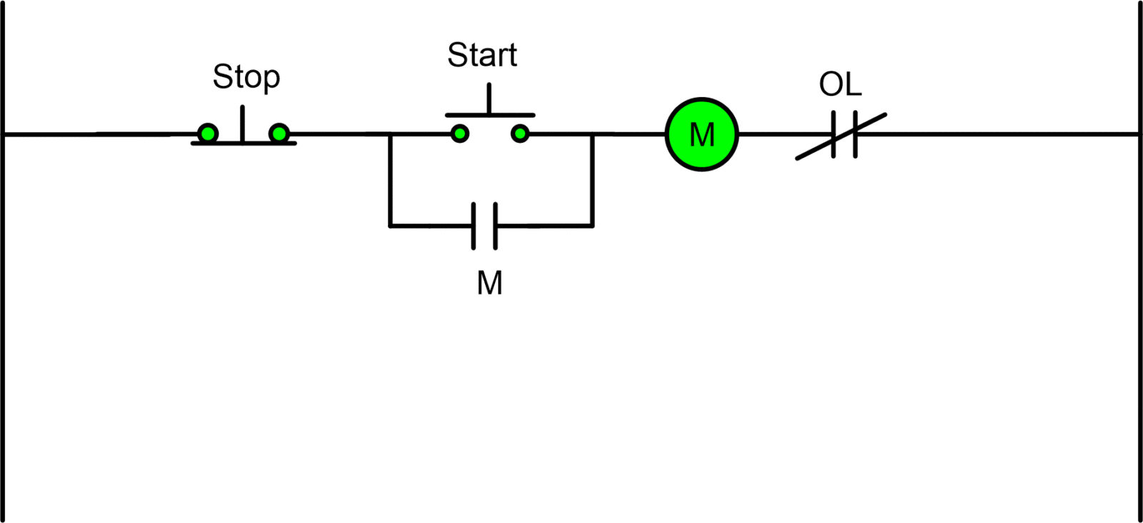
To keep voltage flowing to the coil, a three-wire control circuit employs a momentary contact, start/stop stations, and a normally open seal in contact wired in parallel with the start button.
Because fewer parts are required to operate the load, the setup for the sire control circuit with three wires is distinct from the two-wire operation. While the specifics of each manufacturer’s three-wire device switch may change, the underlying circuit is universal.
Stop/Start Control Circuit Operation

Configuration 3 uses the following logic for its Stop/Start circuit:
- An electrical current is sent to the coil after the start button is pressed.
- The pilot device’s armature and the memory/seal-in contact both close once the coil is activated.
- The coil’s power is kept on by the seal-in contact regardless of whether the start button is held down.
- The motor starter (M) ensures that the connected load receives full line voltage and continues running until the stop button is pressed or the motor overloads.
- By de-energizing the coil and opening the line voltage to the loads, the power is cut off when the stop button is pressed.
Multiple Start/Stop Stations Controlling a Motor
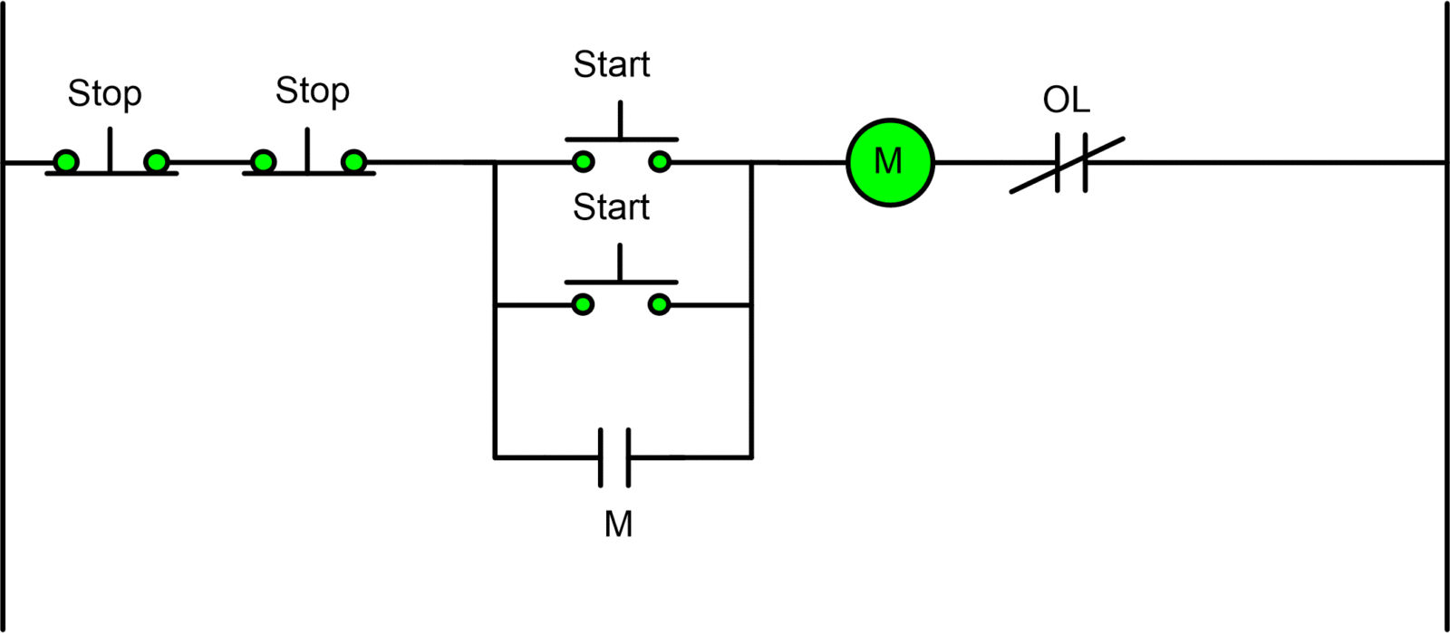
It may be necessary to manage a load from more than one point at a time. The control circuit shown in the diagram below is what is required to carry out the action.
Initially, a NOR logic is established by connecting the stop pushbuttons in series. Next, an OR logic circuit is built out of the start pushbuttons connected in parallel. The three-wire control circuit has been expanded upon in this newer design.

This Multiple Stop/Start circuit in Configuration 4 operates as follows:
- The coil can be activated by pressing either of the start buttons.
- When the coil is energized, the motor starter’s armature closes, along with the seal-in contact that serves to maintain power to the coil, negating the need for the start pushbuttons to be depressed.
- The load connected to the motor starter receives full line voltage.
- Until one of the start buttons is depressed or an overload occurs, the motor starter will keep running.
- After the emergency buttons are depressed, the memory/seal-in contact loses power, and the coil’s armature opens the main contacts.