A clamp meter is a type of device that can create an AC current without contact. Through the flow of current through a wire, a magnetic field is generated.
Current in a circuit can be measured with a clamp-on ammeter by gauging the intensity of the magnetic field surrounding a single conductor. Currents from 0.01 A or less up to 1000 A or more can be read by clamp-on ammeters.
Clamp-on ammeters are commonly used to measure current in circuits with more than 1 A of current and in other situations where the current can be measured by simply clamping the ammeter’s jaws around a conductor.
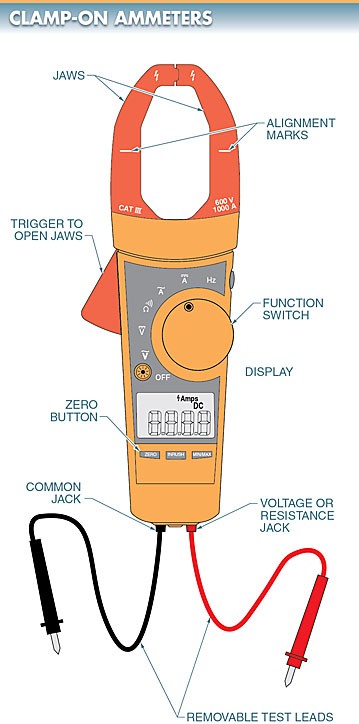
The majority of clamp-on ammeters also measure voltage and resistance. The clamp ammeter should have test leads, as well as voltage and resistance measurement settings. For an example, please refer to Figure 1.

In order to prevent stray magnetic fields from being detected by clamp-on ammeters, electricians should keep the conductors under test as far apart from each other as possible. Multiple readings along the same conductor are required if stray magnetic fields are suspected of influencing a measurement.
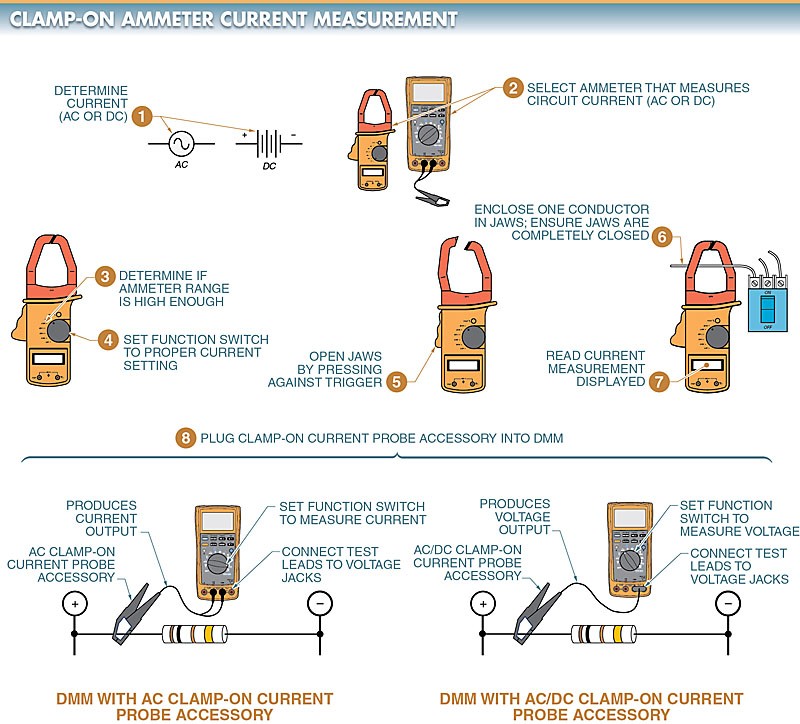
Clamp-On Ammeter Current Measurement.
It is common practice to take AC or DC measurements with a clamp-on ammeter or a digital multimeter (DMM) equipped with a clamp-on current probe. Refer to Figure 2.

How to Use a Clamp Meter to Measure Amps
Establish if alternating current (AC) or direct current (DC) is being measured.
- Choose the appropriate ammeter for measuring the current in the circuit (AC or DC). Choose an ammeter with AC and DC measurement capabilities if you need to take both types of readings.
- To make sure the maximum current in the test circuit can be measured, check the ammeter’s range. Choose an accessory with a high current rating or an ammeter with a higher range if the current being measured is too low. Inspect the ammeter fuses if the ammeter has fused current terminals.
- Adjust the on-off toggle to the correct setting for the current situation (600 A, 200 A, 10 A, 400 mA, etc.). Choose a setting higher than the maximum possible circuit current if there is more than one current position or if the current in the circuit is unknown.
- Just pull the trigger to release the jaws.
- Grab a single wire and squeeze it tight. Make sure the jaws are all the way shut before you take any measurements. It’s important to watch the meter closely to make sure it’s not picking up any unwanted magnetic fields. The test conductors should be isolated from any nearby conductors by at least a few inches. Taking multiple measurements at various points along the same conductor is an acceptable alternative.
- Take in the displayed value as it currently stands.
- Connect the clamp-on current probe to the digital multimeter if necessary. A clamp-on current probe with its black test lead plugged into the universal jack. If you’re using a device that measures current and has a mA jack, the red test lead should go in there. If you’re using a current measuring accessory that has a voltage output, you’ll need to connect the red test lead to the V jack. The current output from current measurement accessories is 1 mA per 1 A of measured current (1 mA/A) and is only suitable for use with alternating current (AC). Measurements of alternating current (AC) or direct current (DC) can be transmitted to a digital multimeter (DMM) at a rate of 1 mV per 1 A of current measured (1 mV/A).
Locating Branch Circuits Using Clamp-On Ammeters.
Before a technician can begin troubleshooting or working on a circuit, he or she must first find that circuit in the switchboard, panelboard, or load center and shut off the power to that section of the building.
Wires in switchboards, panelboards, and load centers are frequently unlabeled or incorrectly labeled. Since turning off a circuit also eliminates any loads that are connected to it, a technician can’t begin turning them off until the correct circuit is located.
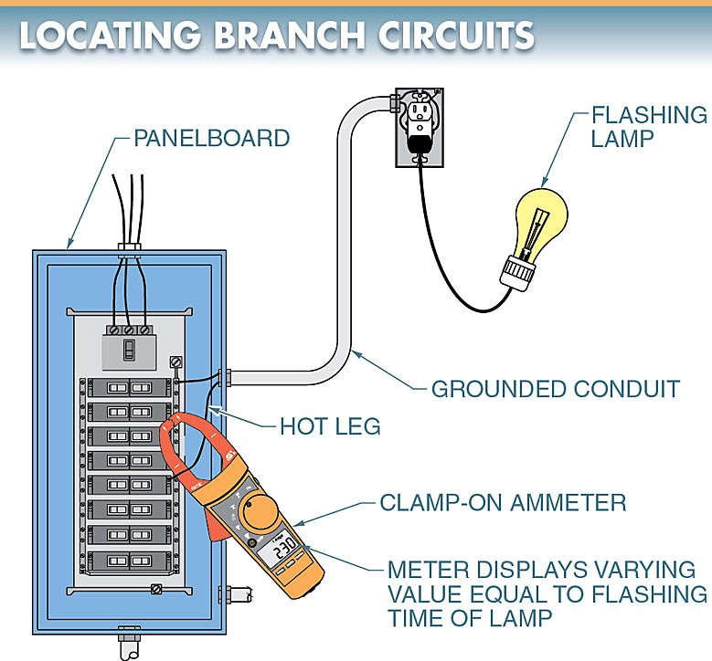
Resetting control devices such as timers, counters, clocks, starters, etc. is necessary to avoid unexpected shutdowns of life-saving apparatus like alarms and safety circuits. In order to cut power to a specific circuit, you can use a flashing lamp and an ammeter clamp. Take a look at the third figure.

Tech Fact
Now, clamp-on ammeters can measure currents from 4 mA all the way up to thousands of amps. It’s also possible to find clamp-on ammeters with detachable display heads for out-of-sight monitoring, flexible cables that bend to connect around bulky conductors and bus bars, and compact jaws with a detachable lead for use in confined spaces.
You can use any outlet on the circuit you’re about to cut off to power the flashing lamp. A clamp-on ammeter is attached to each circuit while the lamp flashes. All circuits, with the exception of the one containing the blinking lamp, show a steady current reading. When you plug an ammeter into the circuit where the blinking light is located, you’ll see a reading that varies in time with the lamp’s blinking rate. As a next step, disconnecting this circuit will allow for easier troubleshooting.