A UPS is designed to provide power to a load device in case of a mains failure. It stores the power in its batteries and then feeds it back to the device in case of a malfunction. Each of these devices has a semiconductor static switch that connects the main AC supply to the batteries.
This post provides an in-depth analysis of the different types of uninterruptible power supplies (UPS), and their applications in power generation, including a discussion of their working principle and operational modes.
The use of an Uninterruptible Power Supply is necessary whenever there are loads that must be powered but cannot be powered directly by the utility supply (mains).
Power instabilities like voltage and frequency swings, as well as superimposed noise, interruptions, and supply failures, are all things that UPS can shield your equipment from.
Computers, process control and monitoring, telecommunications, healthcare facilities, and security systems are some of the most common uses mentioned.
The UPS’s Operating Theory and Components
1. Mains Distribution Unit
It provides input power to the UPS system and distributes Mains (utility) or generator power throughout the building. The bypass supply and rectifier both have their own dedicated power connection to the mains.
The uninterruptible power supply (UPS) system’s “earth” safety connection is also considered to be an integral part of the Mains distribution unit.
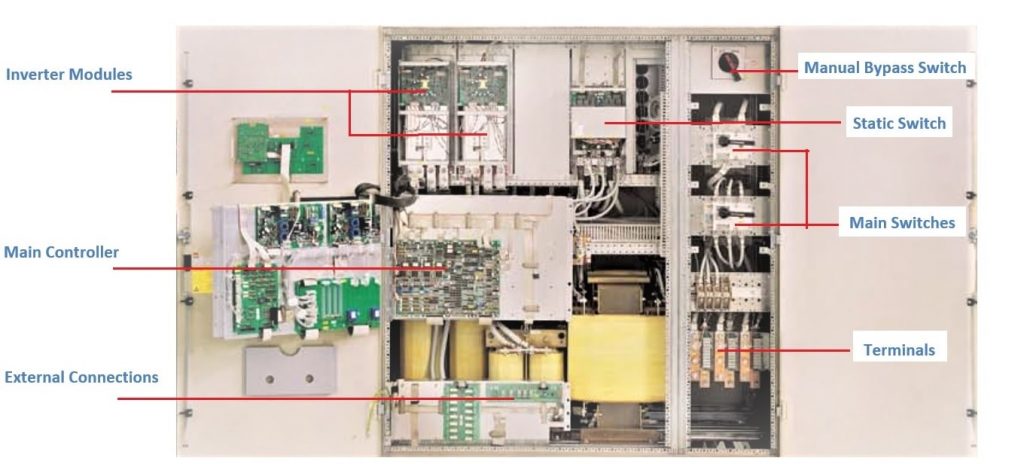
2. UPS Module
There’s UPS in there somewhere (without Battery). An uninterruptible power supply (UPS) module or multiple modules may be used, depending on the setup.
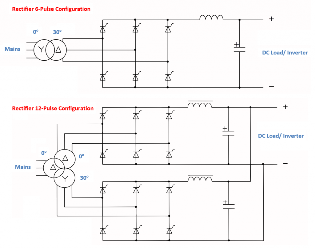
RECTIFIER:
The Rectifier is responsible for providing power to the Battery and the Inverter by converting AC current to DC current using a 6- or 12-pulse thyristor. A 12-pulse thyristor rectifier has a significant advantage over a 6-pulse thyristor rectifier in that the main current distortion is cut by nearly half.
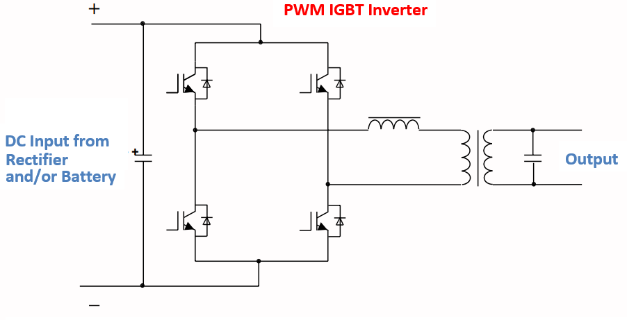
INVERTER:
The inverter’s job is to use an IGBT – pulse width modulated (PWM) inverter module to change the DC current into the AC current.
STATIC SWITCH:
When the static switch is in the “on UPS” position, it connects the inverter’s output to the load using mains power or battery power. When an inverter fault or high inrush occurs, the static switch will switch the load back to bypass. In the case of critical loads, where a delay of even 5-10 milliseconds in switching from bypass to inverter could be disastrous, this is an extremely important consideration.
The static switch’s main benefit is its lightning-fast transfer time—less than four milliseconds.
MANUAL BYPASS SWITCH:
To perform UPS maintenance, a manual bypass switch is used to disconnect the UPS from the rest of the circuit.
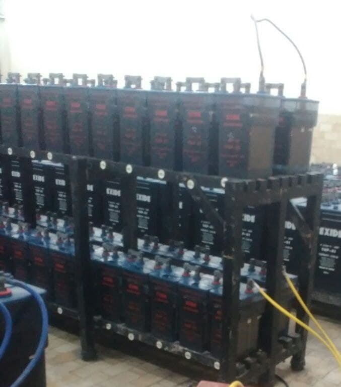
3. Battery Module:
In the event of a power outage, this module contains the battery pack that will power the UPS. Different batteries, such as lithium-ion, nickel-cadmium, nickel metal hydride, etc., are available.
4. Output Distribution Module
Distributing the UPS system’s output among multiple loads is essential. In most cases, switches, fuses, etc., for each load are included in such a module. In order to protect the other loads supported by the UPS from being affected by a fault in one load, it is crucial to coordinate the use of fuses.
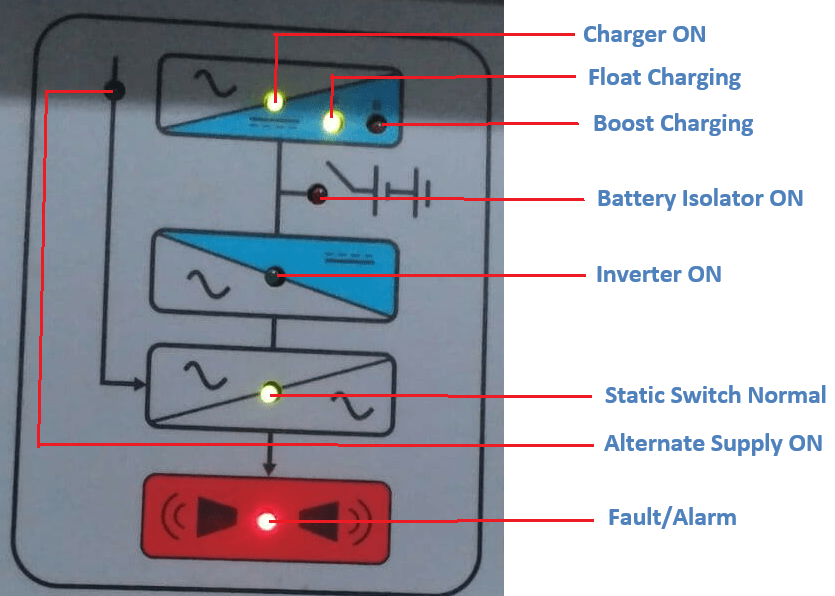
5. Front Panel-LED Mimic Console
The user-specific mimic diagram displays the current operational status of the system, including which system component is currently supplying the load and which is in standby mode.
Principle of Operation and Modes of Work for Power Plant UPS Systems
The Uninterruptible Power Supply, or UPS, can function in one of the following modes, depending on the kind of supply that is readily available.
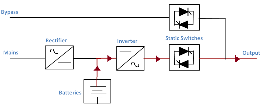
When the UPS Is in Normal Operation
As can be seen in the above diagram, when the Mains are functioning normally, the UPS charges the batteries while also providing power to the load via the rectifier and inverter. Normal mode is currently active.
Using the UPS in battery mode
Uninterrupted power supply (UPS) systems automatically switch to battery mode and supply power to the load via an inverter if the Mains supply fails. As depicted in the following diagram, the UPS can be reset to its original state.
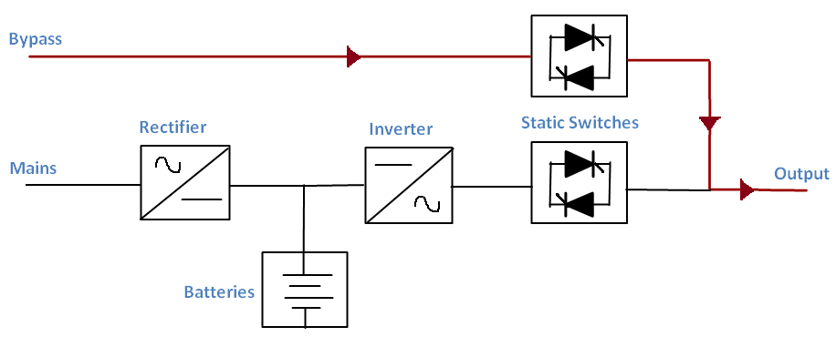
Using a UPS in Bypass Mode
In the event of an inverter overload that continues for a longer period of time than what is considered normal, an output short circuit, or a fault on the inverter, the UPS will switch the load to bypass.
The bypass mode can be activated in two different ways. In the first type, once the problem is fixed, the UPS can be programmed to restart normally. In the latter, the UPS is programmed to revert to normal operation only upon a user-initiated switch.
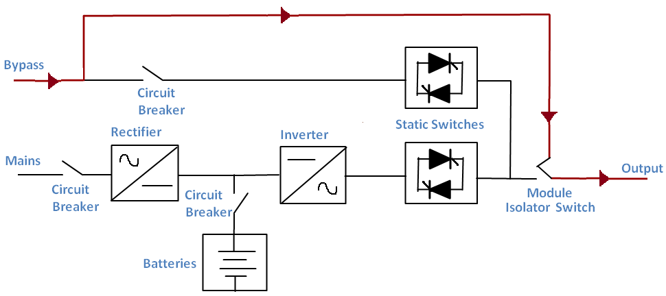
When UPS is in Maintenance Mode
By turning on the UPS’s maintenance bypass circuit breaker, it can be placed into maintenance mode for servicing or repairs. The maintenance bypass power supply will continue to supply the load continuously.
Operating Mode for UPS Parallel
With multiple UPS units working in parallel, the load is automatically distributed across the units. When one component fails, the other takes on its share of the work. If there is an overload, the UPS will switch to bypass mode.