Why is it crucial to determine the short circuit current? As a result, every Electrical engineer needs to conduct studies on short circuit current calculation in order to estimate the value of fault currents and thus to discover the following information.
- For the purpose of calculating the switchgear capacity required for protective relaying
- Find out how much of a dip in voltage occurs when cranking big motors.
- As a means of establishing the appropriate protection equipment rating, MCC, and breaker panel ratings.
Explain why the MVA approach is better than other approaches.
Short circuit parameters can also be determined using the Ohmic and Per Unit Methods. Both of these techniques use complicated conversion formulas that are difficult to memorize.
Unlike the Ohmic method, which requires converting impedances between voltages, the MVA method does not require any such conversions. In contrast to the Per Unit method, no minimum MVA value is needed here. Therefore, the MVA Method is a fast and easy method for performing calculations by hand.

Using the MVA method to determine the current in a short circuit
Here’s how it’s done:
- Transform a regular line diagram into an MVA representation.
- Reducing the complexity of an equivalent MVA diagram to a single MVA value at the fault location.
The next three steps will show you how simple it is to accomplish this.
The first stage entails changing all single-line components to short-circuit MVAs.
The MVA technique is put to use by breaking the circuit up into its constituent parts and then computing each part with its own infinite bus. A separate MVA rating and an impedance or reactance rating are typically assigned to individual pieces of machinery.
Each component’s short circuit MVA in the specified SLD is calculated by dividing its MVA rating by its own per unit impedance or reactance.
Second, add up everyone’s MVA scores.
- Multiple MVAs in series are combined as a single resistance.
- Numerical addition of parallel MVAs.
Third, from the simplified MVA diagram, determine the MVA value at the location of the fault.
Using the MVA quantities obtained in the previous step, simplify the equivalent MVA diagram to produce a reduced MVA diagram.
Example of Short Circuit Current Calculation:
In the SLD below, we see a sample network for a power system.

Factors of SLD:
1.Generator-A:
10 MVA, 10% reactance
2. Generator-B:
5 MVA, 7.5% reactance
3.Transformer:
15 MVA, 5% reactance, 11/33KV
4.Transmission Line:
Impedance Z = 5+j20 ohms
If a symmetrical fault between phases occurs at nodes F1 and F2, determine the short circuit MVA and fault current values fed to the fault.
- The transformer F1’s high-voltage terminals.
- Near the end of transmission line F2’s load.
Using the MVA Approach to Solve the Presented Network:
Here we will examine the MVA Method for determining the fault current at points F1 and F2.
Using the three-step method described above, the answer is provided below.
Step-1:
Perform a short circuit MVA conversion on every single line item in the provided SLD.
1 – A Generator:
10 MVA, 10% reactance
Generator Short Circuit MVA MVA1 = MVA / Generator Sub-Transient Reactance
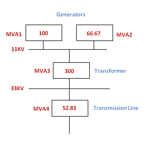
MVA1 =10/0.1=100
2. Generator-B:
5 MVA, 7.5% reactance
Short Circuit MVA of Generator B MVA2 = MVA/Sub-transient reactance of generator in per unit
MVA2 =5/0.075=66.67
3. Transformer:
15 MVA, 5% reactance, 11/33KV
Transformer MVA3 MVA3 Short Circuit = MVA/Impedance in per unit
MVA3=15/0.05=300
4. Transmission Line:
Impedance Z = 5+j20 ohms
Z= sqrt(55+2020)
Z= sqrt(25+400)
Z=sqrt(425)
Z=20.615 ohms
Voltage rating of Transmission line= 33KV
Short Circuit of MVA of Transmission Line MVA4 = KV2/Impedance in ohms
MVA4= 33*33/20.615 = 52.83
SLD Equivalent MVA Diagram:
Using the data provided for the Short circuit MVA of each SLD component, the MVA diagram can be created.

Step-2:
Add up the MVAs of each person.
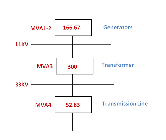
There are two generators hooked up in parallel.

Combined MVA1-2= MVA1 + MVA2 = 100 + 66.67 =166.67
Step-3:
The SC MVA and SC Current can be determined by simplifying the MVA diagram into a single value at the point of fault.
1. Method for Determining the Short Circuit MVA and Current Caused by Fault F1
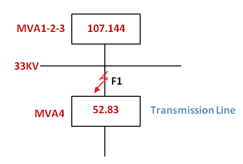
MVA1-2 is in series with MVA-3

Total Short circuit MVA up to the fault F1= Combined MVA1-2-3= (MVA1-2 * MVA3)/ (MVA1-2 + MVA3)
MVA1-2-3= (166.67 *300)/ (166.67 +300) =107.144
- Total Short circuit MVA up to the fault F1=107.144
- Short Circuit Current at F1 = Total Short circuit MVA up to the fault*1000/ (1.732 * KV) = 107.144*1000/ (1.732*33) =1874.58A
2. Short Circuit MVA and Short Circuit Current Calculation for Fault F2:
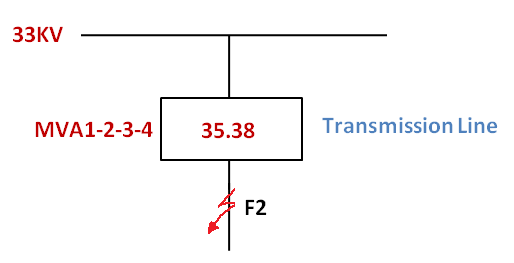
MVA1-2-3 and MVA-4 are in series.

Total Short circuit MVA up to the fault F2= Combined MVA1-2-3-4= (MVA1-2-3* MVA4)/ (MVA1-2-3 + MVA4)
MVA1-2-3-4= (107.144*52.83)/ (107.144 +52.83) =35.38
- Total Short circuit MVA up to the fault F2=35.38
- Short Circuit Current at F2 = Total Short circuit MVA up to the fault*1000/ (1.732 * KV) = 35.381000/ (1.73233) =619A
By using the straightforward MVA approach, we can easily determine the short circuit MVA and current values for any given network topology and fault condition.