The term transformer protection can be used to describe various types of devices that are designed to protect an electrical or mechanical component from various threats. These include the sensing of current through the transformer, as well as the monitoring of various operational parameters such as oil pressure and temperature.
Let’s examine the significance of the topic of transformer protection before diving into the specific types of protection available.
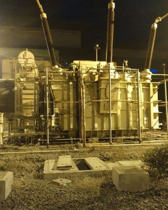
Various Types of Transformer Protection
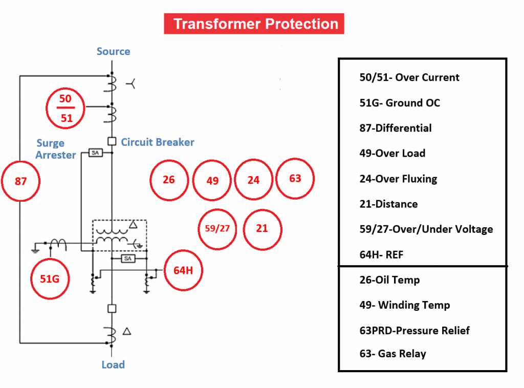
There are two main categories of transformer protection. Protection from electrical hazards is one option, and it’s typically built around considerations of things like current, voltage, frequency, and impedance. Mechanical protection is the second form of defense, and it is developed in response to mechanical factors like temperature, pressure, density, and so on.
1. Electrical Transformer Shielding Varieties
- Over Current/Earth Fault-50/51Protection
- Under Impedance/Distance relay Protection-21
- Differential Current Protection-87
- Restricted Earth fault Protection-64H
- Three Phase Overload Protection-49
- Over Fluxing Protection-24
- Over Voltage-59/Under Voltage-27 Protection
2. Mechanical Shielding for Transformers:
- Marker for Oil Temperature-26
- Gradient of Wind Speed and Direction-49
- Relief from Oil Pressure-PRV-63PRD
- Using a Buchholz Relay for Gas Accumulation-63
Mechanical Safety for Transformers
1. Relay for Oil Temperature Trip
When an internal fault, such as insulation failure in one phase of winding and shorted, or a local hotspot is generated, the oil temperature is sensed by the relay because the oil has been heated by the transfer of heat from the source. This oil temperature relay triggers when the oil temperature rises above a predetermined threshold.
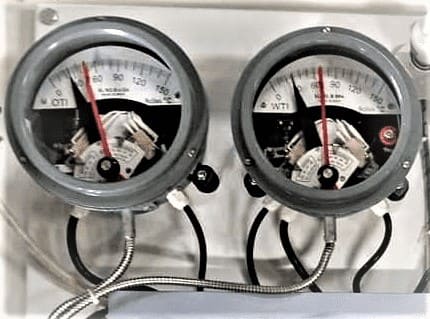
2. Trip Relay for Winding Temperature
The winding temperature indicator displays a value that is proportional to the transformer’s top oil temperature and the current through the windings. Two or four mercury switches are included with the indicator. The first one is for the alarm, the second for the trip, the third for the fan, and the fourth for the pump. To facilitate differentiation, each switch has a unique temperature setting.
If the temperature goes above the limit. The transformer is de-energized when the trip contact is actuated at the desired temperature.
3. PRV (Pressure Reducing Valve)
If the transformer fails catastrophically, the internal pressure could build up and cause the tank to explode. A Pressure relief valve is installed on the transformer to prevent just this kind of emergency. In most installations, the PRD valve (pressure relief device) is situated atop the transformer.
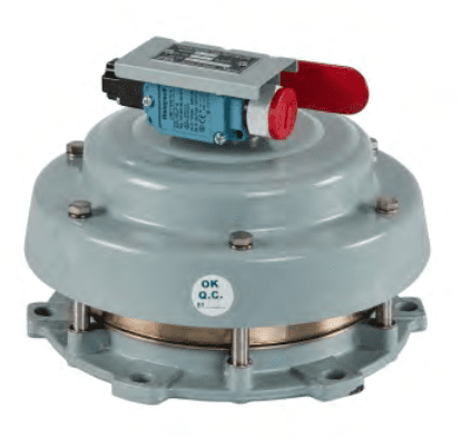
When the internal pressure of a transformer rises above the preset limit, the pressure safety valve PRD releases the pressure by opening the valve clap, which is held closed by a spring. The pressure valve clap returns to its original position and fully closes after the pressure drops.
4. Buchholz Relay
It operates similarly to a gas-actuated relay. The Buchholz relay in a working transformer is completely submerged in oil. Gas bubbles are produced in the transformer tank and gas accumulates in the relay chamber en route to the conservator in the event of any internal fault.
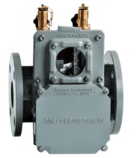
A double element relay like this one can identify both small and large problems with a transformer. After a certain amount of gas has accumulated, the first (alarm) component will activate. A rapid loss of oil indicates a serious fault within the transformer, setting off the second (trip) element.
Protection from Electrical Surges in Transformers
1. Safety from Excessive Current and Earth Faults
For transformers with ratings of less than 10 MVA, HRC fuses are typically used. In the absence of differential protection, overcurrent relays are the first line of defense above that threshold. Overcurrent protection is used as a secondary measure if differential protection is employed.
The Earth fault overcurrent protection kicks in if the current in any phase is higher than the preset limit.
OC Shields Come in a Few Varieties
- 50 – Instantaneous Overcurrent
- 51 – Time’s Overcurrent Phase
- 50G – Ground Fault Instantaneous
- 51G – Ground Fault in Time/Earth Fault in Standby
- Relay settings for overcurrent (50) and ground fault (51) protection
The following scenarios are safe for overcurrent relays to operate in.
- At the time of the magnetizing inrush current, which occurs whenever the load is switched on or off, the load experiences an extremely brief but extremely powerful current surge.
- Load for a limited amount of time, especially when the temperature is low, is recommended to prevent the circuit breaker from tripping.
- A through fault is a fault that the OC relay does not detect before triggering other protection mechanisms, such as in the case of a 3-phase short circuit on the load side.
- When an overload on a three-phase circuit reaches a permitted value, the overcurrent relay should not trip.
- Many different configurations for connecting in the event of an overcurrent or earth fault
2. Protected by an Impedance/Distance Relay
There is no need for backup protection for network-connected transformers if they are equipped with OC protection. When the maximum and minimum short circuit fault MVA are very different, Under Impedance or Distance relay protection is essential.
3. Current Differential Protection
The phase currents on either side of the transformer are compared by the differential protection relay. If the phase current differential in one phase is greater than the value set for the instantaneous protection stage or stabilized operation characteristic of the function, the relay will activate.
Differential protection relies on over-current safeguards as a failsafe.
The transformer is safeguarded by differential protection against
- Windings have short circuit faults.
- Faults between the turns.
The diagram below shows how differential current protection can be applied to both generator transformers (GT) and unit transformers (UT).
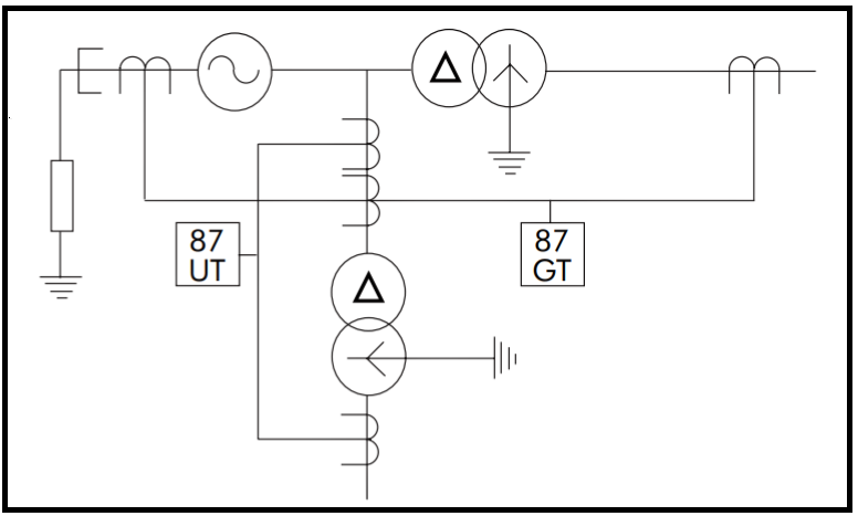
Differential protection by means of a relay is explained in detail.
Relay with Differential Safety Mechanism
4. Protection From Earth Faults Is Limited To
Only 80% of the winding is safeguarded by differential protection; the remainder is covered by REF. To put it simply, it prevents damage to the transformer winding in the event of an accidental ground.
The area between the earthed Neutral Terminal of the transformer and the Star side winding is protected by a reference electrode field (REF). Protection is limited to just this area because of where the fault current is being detected.
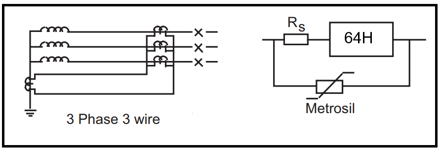
- In resistive earthing, the earth fault current is sensed by the external CT or by the bushing CTs on the phases and the neutral side.
- A set of Phase Current Transformers, a Neutral Current Transformer, Metrosil, and Stabilizing Resistors are used to implement REF protection, as described in greater depth here.
- Safety from Earth Faults in the Presence of High Impedance [64H]
5. Power System Protection Against Overloading on Three Phases
Prevents any potential harm from occurring under overload conditions.
A thermal overcurrent relay is used for overload protection (49). These relays base their inverse time characteristics on the transformer’s thermal time constant and the IMAX continuous overload current.
6. Safety from Excessive Fluxing
Transformers are easily damaged by overheating due to excessive fluxing or excitation. For transformers that could be damaged by operating at an unsafe voltage or frequency, a V/Hz Over excitation relay can be installed. Transformers used in generators can become overexcited when the turbine is being accelerated or decelerated. In order to avoid damage, the V/F ratio should not exceed 1.1 times the rated value.
7. Anti-Overload Circuit
Relays for over and under voltage protection shield against dangerous fluctuations in phase voltage.