Similar circuit diagrams for a basic parallel circuit are shown in Figure 1 drawn in two different ways. Horizontal or vertical lines, like in Figure 1, represent the interconnecting conductors in a circuit diagram (a). However, we combine the junctions that are directly connected to each other to show the nature of a parallel circuit, as shown in Figure 1. (b).
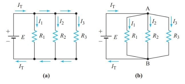
Connections between the parts allow us to recognize a parallel circuit. Parallel lines are shown in Figure 1 for the segments E, R1, R2, and R3. These segments all share a common connection to points A and B. V1 = V2 = V3 = E because all of the resistors are in series across the power supply. Since the voltage is shared by all components in a parallel circuit, we don’t need to use subscripts.
Parallel Circuit Definition
Two or more electric components are in parallel in an electric circuit if a common voltage appears across all of the components.
To calculate the circuit current, we measured the total resistance of the series arrangement. To calculate the circuit’s resistance in a parallel circuit, we must first find the total current.
Ohm’s law can be used to calculate the current in each branch of the circuit in Figure 1 given the applied voltage and the values of the individual resistances.
If we visualize electrons flowing through each branch, we can see that the current through the source is simply the sum of the currents in the branches.
When multiple branches are connected in parallel, the total current equals the sum of those branch currents.
IT = I1 + I2 + I3 + … (1)
Equivalent Resistance Calculation Example 1
In Figure 1, we’ll pretend that R1 is 40 Ω, R2 is 30 Ω, R3 is 20 Ω, and E is 120 V. How much current would be drawn from the source by a single resistance?
Solution:
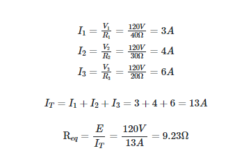
It is impossible to have a series circuit with a resistance less than the sum of its resistors. In contrast, the resistance of a parallel circuit (such as the combination of resistors in Example 1) is less than the resistance of any single resistor. Due to this, total resistance is not a relevant concept when discussing parallel circuits. Req, the equivalent resistance, is used to describe the resistance of two or more parallel resistors.
There are many ways in which the properties of series and parallel circuits are similar but opposite from one another.
Kirchhoff’s Current Law
Kirchhoff generalized Equation 1’s total-current principle to all electric circuits.
Kirchhoff’s current law: At any junction in a circuit, the algebraic sum of the currents entering the junction equals the algebraic sum of the currents leaving the junction.
Current in Parallel Circuit Example 2
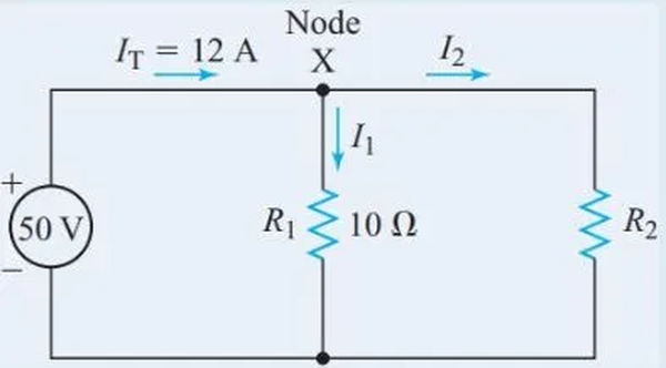
Calculate the current flowing through R2 in the circuit shown in Figure 2.
Solution:

IT is the current entering junction X and I1 and I2 are the currents exiting junction X. Therefore,

Conductance
The total current in a parallel circuit is always greater than the current through any of the branches, as shown in Examples 1 and 2. The equivalent resistance is always less than the lowest resistance in a branch because of this. The equivalent resistance decreases as the number of paralleled resistors increases.
To rephrase, a circuit’s current-carrying capacity improves as more resistors are connected in parallel, because more parallel branches are available.
Conductance is a measure of the ability of an electric circuit to pass current. The letter symbol for conductance is G.
The SI unit for conductance is the Siemens (S): ![]()
Conductance is the reciprocal of resistance:

Where G is the circuit’s conductance in Siemens and R is its resistance in ohms.
For simple parallel circuits, E and V can be divided equally, so we get by dividing both sides of Equation 1 by either one.

Substituting Ohm’s law into Equation 2 gives

GT = G1 + G2 + G3 + ⋯ (3)
A parallel circuit’s total conductance is simply the addition of the conductances of its individual branches.
Req = 1/GT is a simple formula for calculating the equivalent resistance.
Conductance allows us to determine the equivalent resistance in a parallel circuit without needing to determine the total current flowing through the circuit.
Example 1A
In Figure 1, we’ll pretend that R1 is 40 Ω, R2 is 30 Ω, R3 is 20 Ω, and E is 120 V. How much current would be drawn from the source by a single resistance?
Solution

Equation 3 changes to reflect the case where only two resistors are connected in parallel.

And,

The equivalent resistance of two parallel resistors is the product of their resistances divided by the total resistance of both.
By manipulating Equation 4, we can determine the value of resistance R2 that must be connected in parallel with resistance R1 to achieve the target equivalent resistance value.

Using Ohm’s law and Kirchhoff’s current law, we can calculate the current flowing through resistor R2:
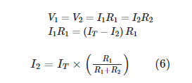
It can be demonstrated that when N identical resistors are wired in parallel,

In this case, the resistance of each parallel resistor, R, is multiplied by the total number of resistors, N, to get the total resistance.
Example 3
What is the equivalent resistance of a 1-kV and a 4-kV resistor in parallel?
Solution:

The term “resistivity” was coined by us to describe the resistance of a material as measured in terms of its length and cross-section. That’s also how we define conductivity.
A substance’s conductivity can be defined as its conductance per unit length and cross section. Greek letter phi represents conductivity (sigma). Conductivity is measured in Siemens per meter.
Since conductance is the reciprocal of resistance, conductivity is the reciprocal of resistivity:

Characteristics of Parallel Circuits
With R equal to 1/G and V equal to I/G, we have the following. All components connected in parallel share the same voltage.

Each set of equivalent terms can be obtained by transposing one of the variables.

In a parallel circuit, the ratio between any two branch currents equals the ratio of their conductance or the inverse of the ratio of their resistances.
Example 4
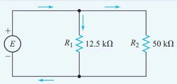
When connected in parallel, a 12.5 kV resistor and a 50 kV resistor draw 15 mA of current. Determine how much current is passing through the 50 kilovolt resistor.
Solution
The schematic shown in Figure 3 reveals the following.

Substituting for I1 in the first equation gives

Changing the resistance of one leg of a parallel circuit has no effect on the voltage across the circuit or the current through the other legs when the source’s internal resistance is small. Since each individual branch in a parallel circuit operates independently, the effects of a change in one branch are minimal in comparison to the whole.
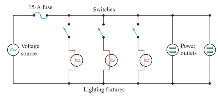
Lighting circuits in a home are typically wired in parallel so that turning one circuit on or off does not affect the functioning of the other circuits (see Figure 4).
Parallel circuits can be identified by the following features:
- Every part has the same voltage.
- The total conductance is the addition of the conductances of all the branches:
GT = G1 + G2 + G3 + ⋯
- A circuit’s total current is the sum of the currents in its various branches.
IT = I1 + I2 + I3 + ⋯
- Comparing branch currents yields the same results as doing the inverse of measuring the resistance between the branches.
- If the voltage across the parallel circuit stays the same, each individual branch operates independently of the others.
Cells in Parallel
Compared to a single cell, the EMF of a battery consisting of identical cells connected in parallel (see Figure 5) is the same, but the maximum current it can supply is higher.
The battery’s overall power output is directly proportional to the number of cells. Cells with lower EMFs will act as loads for those with higher EMFs, resulting in current flow between the cells.
To power the motors in small devices like cordless electric razors, standard AA-sized cells are sometimes connected in parallel to create a compact battery.
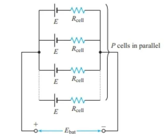
Figure 5 shows the relationship between the number of cells in parallel, P, the electromotive force (EMF) of each cell, and the internal resistance of each cell, Rcell. electromagnetic field produced by a battery is
Ebat = E
as well as the battery’s overall internal resistance is

Example 5
How much current would flow from a parallel-connected battery of ten cells, each with an EMF of 1.50 V and an internal resistance of 0.20 V, through an external resistance of 4.00 V? Get the battery’s terminal voltage.
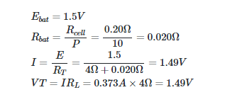
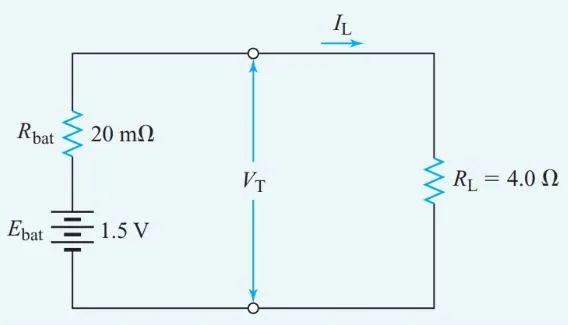
Figure 6 shows an equivalent circuit for the battery.
