A flip-flop is a special kind of digital device that combines the functions of two logic gates. You can’t have digital electronics without flip-flops. They are the fundamental building blocks of timers, chronometers, sequencers, and memory storage devices.
In electronics, flip-flops are used when only one of two states is required to operate reliably. The R-S and J-K varieties of flip-flops are two of the most common.
R-S flip-flop
Figure 1: Have a look! An operational flip-flop is constructed from two NAND gates and two NOT gates. Additionally, a flip-flop has been set up from two NOR gates.
R, S, Q, and /Q are the usual markings for a pin; the /Q is pronounced “Q not.” Set-reset flip-flops, also known as R-S flip-flops, are a specific type of R-S flip-flop. Set, on the other hand, refers to the S pin, while reset, on the R pin, refers to its opposite..
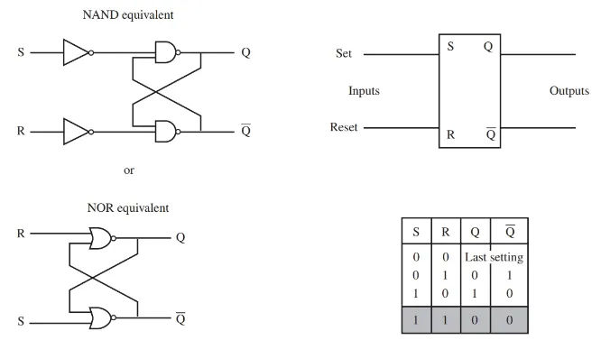
To use an R-S flip-flop requires little more than understanding the terminology. When S is large, so is /Q. If R is high, then so is Q. If both inputs are at their minimum, the output will reflect the state of the last input. If both inputs are high, the value is not acceptable. If both inputs are high, there is no way to predict the output.
One can also see an R-S flip-flop truth table in Figure 1. A flip-flop works on the simple principle that its two outputs cancel each other out. When one output is high, the other must be low; this is what we mean when we say that two outputs are complementary. A flip-flop can remember its previous output state.
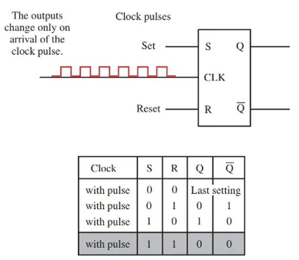
The outputs of a clocked R-S flip-flop are timed in sync with an external clock. Figure 2. When the R or S input is altered and the clock input receives a pulse, the output of the clocked R-S Flip-flop will transition.
Millions of individual digital components can function as a single entity when synchronized by a central clock. A digital clock is a series of pulses that goes from high to low in a continuous cycle. Most digital systems rely on a pulse train as their central nervous system.
With an R-S flip-flop, the output state is preserved even if the input is no longer present. Since this is the case, the clocked R-S flip- flop is a useful memory device.
J-K flip-flop
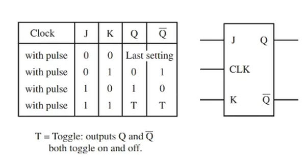
When it comes to how they function, the J-K flip-flop and the R-S flip-flop are very similar. Like the clocked R-S flip-flop, the J-K flip-flop is driven by a clock. If two lows are applied to the inputs of a J-K flip-flop, the output will not change. If both inputs are set to “high,” the outputs will alternate between being on and off. For more information, please refer to Figure 3.
D flip-flop
In Figure 4 we see a D flip-flop, which is very similar to the J-K flip-flop except that it only needs one input, while the J-K flip-flop needs two.
After a clock signal is applied and an input signal is received, the Q outputs will toggle. The values of Q and /Q at their respective outputs will remain in a holding pattern until the clock signal arrives.
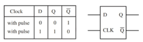
In contrast to the R-S and J-K flip-flops, the D flip-flop can never be in an unknown state, as evidenced by a comparison of their respective truth tables.
Both the R-S flip-flop and the J-K flip-flop require knowledge of the previous state to determine the output state. The D flip-flop design eliminates these issues.
The signal from a D flip-flop The Q-phrase is universally regarded as complimentary. The addition of a NOT gate to the J-K flip-inputs flop’s transforms it into a D flip-flop simulator.
There are a lot of flip-flops in binary counters. It can be seen that the outputs of the R-S, clocked R-S, D flip-flop, and J-K flip-flop are all set to 1. They continually transition between the two states. One’s Q value is either high or low. You can see how the flip-flops could serve as the brains of a binary counting system, given that the binary number system consists of only 0s and 1s.