Calculating total resistance, current, and power in an AC circuit is covered, along with several solved examples.
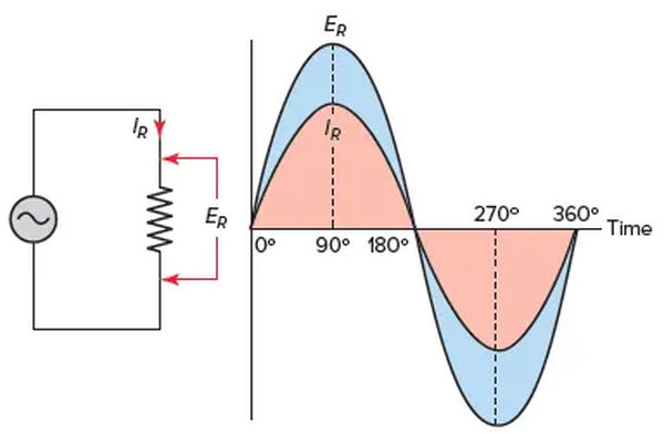
Application of an alternating voltage to a circuit results in the flow of an alternating current of the same frequency. It can be seen in Figure 1 that the voltage and current in a purely resistive AC circuit are in phase with one another.
When the voltage and current both start from zero and rise to their maximum values at the same instant, they are said to be in phase with one another. Therefore, there is no phase difference between in-phase waves.
The behavior of purely resistive circuits is essentially the same for both alternating current and direct current. Pure resistive loads consist of things like incandescent lighting and resistance heaters. Because they generate heat and have current and voltage that are in phase with one another, resistive loads are easily identified.
From a theoretical standpoint, it is impossible for an alternating current circuit to consist entirely of resistance. Because of how little other properties can change the circuit’s voltage and current, it can be considered purely resistive.
In most cases, the rules and formulas that govern DC circuits also apply to AC circuits. What’s more, the rules work the same way for AC resistive circuits. In this case, it is true because resistors are linear components whose characteristics are independent of frequency.
Both the current and the voltage in a resistive DC circuit are constant. The current and voltage in a resistive AC circuit alternate in lockstep. For an alternating current circuit, Ohm’s law can be written as
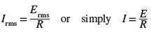
All references to AC voltage or current are to effective or rms values unless otherwise specified. For an alternating current (AC) circuit, this leads to the following formulation of Ohm’s law:
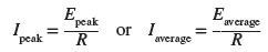
It is crucial to remember that you should not mix AC values when solving for quantities in AC-resistive circuits. In order to solve for effective values, all of the input values must also be effective values. Equally, when solving for an average or peak value, you can only use values that fall into that range.
Total Resistance in AC Resistive Circuit Example 1
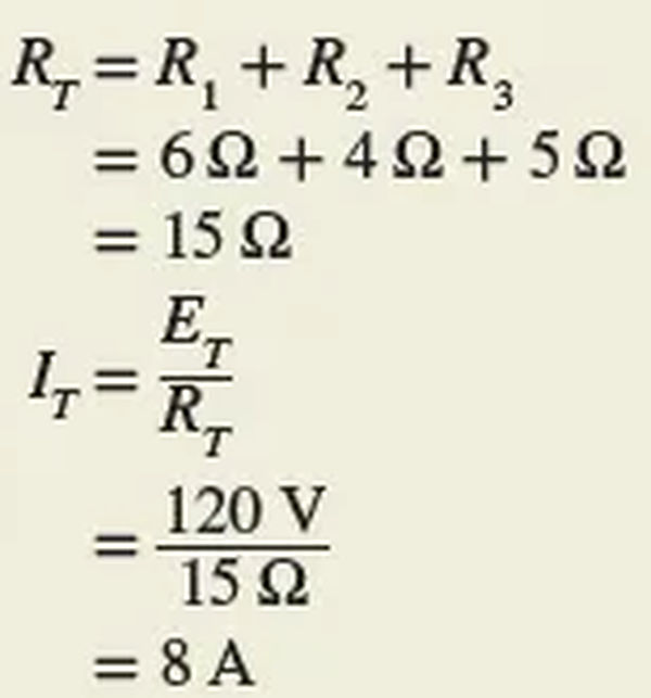
An alternating voltage source of 120 V is connected in series with three resistors (R1 = 6 Ω, R2 = 4 Ω, and R3 = 5 Ω) as shown in Figure 2. Find the circuit’s total resistance and the actual value of the current flow.
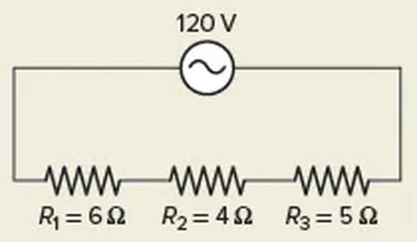
Solution:
Power (P) in a direct current (DC) circuit is defined as voltage multiplied by current (I). Even in an alternating current (AC) circuit, resistance exists when the current and voltage are in phase. When using an alternating current, the current and voltage values shift over time. The power is the product of the voltage times the current at a given time.
Plotting all the instantaneous powers, as illustrated in Figure 3, produces a power waveform. Take note that the positive power waveform only appears for in-phase currents and voltages. When applied to a negative voltage, a positive power is generated from the negative current. This means that the resistive load is converting electric energy into heat energy during the complete cycle. Then the power dissipated in a purely resistive load fed from an AC rms supply is the same as that for a resistor connected to a DC supply and is given as

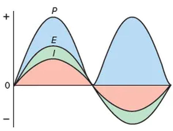
The effective or rms current and voltage are denoted by I and E, respectively.
Total Power in AC Resistive Circuit Example 2
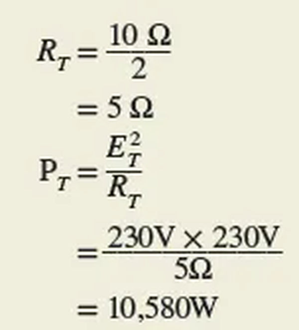
Determine the true total power used by the single-phase resistive circuit depicted in Figure 4.
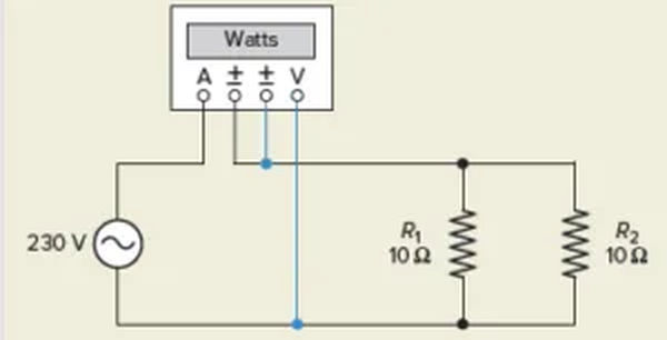
Solution :
Similar to single-phase analysis, voltages and currents in three-phase resistive circuits are typically expressed as rms or effective values. Using the following formula, we can determine the power in watts that is transmitted to three-phase balanced resistive loads.
Power is Resistive Circuit Example 3
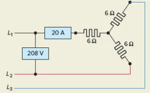
Figure 5 shows a balanced three-phase resistive heating load circuit. The problem is to determine the total power actually used by the load.
Solution:

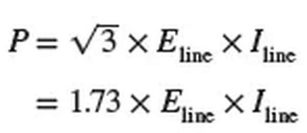
Since it is more convenient to measure the line voltage and current in a three-phase system, it is commonly used to calculate the power supplied by the circuit in terms of these two variables.
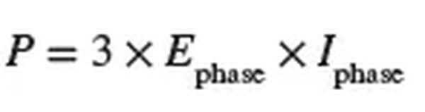
While this is true, in a three-phase balanced resistive system, the total circuit power is also equal to the sum of the power of each phase, or three times the power of one phase:
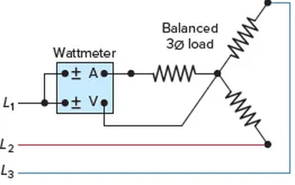
To illustrate how to measure the three-phase power of a balanced three-phase resistive load bank, Figure 6 depicts the connection of a single wattmeter. The wattmeter is hooked up to measure the voltage and current in each phase. When all three phases are in harmony, the total power output is equal to three times the value read from the wattmeter.
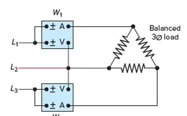
In single-phase systems, the line current and voltage can be metered with two separate wattmeters to calculate the three-phase power consumption. Power in three-phase systems can be measured using the so-called two-wattmeter method, which is depicted in Figure 7.
Total circuit power is equal to the sum of the two wattmeter readings, W1 and W2, if the three-phase system is balanced and resistive, and the wattmeters read the same. When connecting wattmeters, be sure to follow the polarity marks (±) on the voltage and current coils.
Review Questions
- In an alternating current (AC) resistive circuit, what is the phase relationship between the voltage and current?
- What form of energy is converted by all resistive loads?
- A heater with a 10-ohm resistance is powered by 340 V peak-to-peak alternating current. Determine:
- The voltage’s maximum reading.
- The voltage’s actual useful value.
- Heating system’s wattage.
- Two 4-ohm resistors are connected in series with a 24-volt direct current (DC) source.
- The total resistance and current must be calculated.
- It should be done again with a 24-volt AC source and the same circuit.
- The heating element in a furnace that operates on 240 volts ac is actually four 20-ampere elements wired in parallel. Figure out the unit’s kilowatt rating.
- It is determined that a balanced three-phase wye-connected resistive load bank receives 415 volts of line voltage and 30 amperes of line current.
- How much electricity is being transferred across a single load bank phase?
- How much current is flowing through a single load bank phase?
- How much money is the total kilowatt-hours (kW) of power delivered to the load bank worth?
- What would the kW reading be on a single wattmeter that was connected to measure the voltage and current of just one phase?
- It is determined that 480 volts and 104 amperes of line current are supplied to a balanced three-phase delta-connected resistive load bank.
- How much money is the total kW power delivered to the load bank worth?
- What would the kW reading of W1 and W2 be if the power was measured using a pair of wattmeters?
- Check out the difference between the voltages provided by a four-wire 208 wye connection and a 480 wye connection.
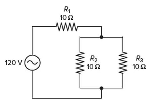
- Determine the voltage, current, resistance, and power for the AC circuit depicted in Figure 8. Make a table to organize your answers.
10. In a synchronous AC generator, the rotor’s magnetic field is energized in a way that is different from an induction type.
Review Questions – Answers
- They are perfectly in sync with one another.
- They are a heat source.
- (a) 170 V, (b) 120 V, (c) 1440 W
- (a) RT = 8 Ω, IT = 3 A, (b) RT = 8 Ω, IT = 3 A
- RT = 5Ω, PT = 11.52 kW
- (a) 240 V, (b) 30 A, (c) 21.6 kW, (d) 7.2 kW
- (a) PT = 86.6 kW, (b) W1 = W2 = 43.2 kW
- 208 V and 120 V or 480 V and 277 V
| Voltage | Current | Resistance | Power | |
| R1 | 80 V | 8 A | 10 Ω | 640 W |
| R2 | 40 V | 4 A | 10 Ω | 160 W |
| R3 | 40 V | 4 A | 10 Ω | 160 W |
| Total | 120 V | 8 A | 15 Ω | 640 W |
10. Either permanent magnets attached directly to the rotor of the synchronous generator, or an external DC current flowing through the rotor field windings, are used to generate the rotor’s magnetic field. The field excitation for an induction generator comes from the power grid.