Numerous manufacturers and features give oscilloscopes their distinctive characteristics. You can divide oscilloscopes into two broad categories, as shown in Figure 1a and b: those used for general-purpose bench work applications, and the more complex (and expensive) laboratory-quality oscilloscopes. In Figure 1c, we see a handheld scope.

Figure 1: (a) General-purpose oscilloscope; (b) lab-quality oscilloscope; (c) portable oscilloscope (Photos courtesy of Tektronix, Inc.)
Oscilloscope data storage (DSO) is depicted in Figure 2a. These are ubiquitous in modern society. It is possible to store signal waveforms in these scopes’ memories for later retrieval and display. This level of detail is useful for a wide variety of applications, including side-by-side comparisons of waveforms over time and space, analyses of complex, long- and/or short-term signal changes, and many others. Analog real-time (ART) scopes aren’t equipped to handle these kinds of analyses.
What you see on the scope is actually occurring at this very moment, which is what the “real-time” designation means. This scope “digitizes” analog signals by repeatedly sampling their levels throughout the waveform’s duration. The electronic information is then stored in a database until it is needed.
At least one well-known oscilloscope manufacturer has been touting a new generation of scopes with “automatic measurements,” graphical user interfaces, the ability to save images to disk, computer connectivity, and other fantastic features.
These scopes boast real-time displaying, storing, and analyzing of complex signals in three dimensions (signal amplitude, signal time, and signal amplitude distribution). As a result of these features, this type of scope is superior to both analog real-time (ART) and digital storage (DSO) oscilloscopes. To view an example of this kind of scope, refer to Figure 2b.
Compared to their analog predecessors, modern digital oscilloscopes make it much simpler to measure complex waveforms. Selecting automated measurements is a breeze with the help of the front panel buttons and on-screen menus.
Amplitude, period, rise, and fall times can all be measured with little effort. Some of today’s scopes can even do some basic math for you, such as calculating the mean, the root mean square, the duty cycle, and so on. On-screen alphanumeric readouts appear for automated measurements made with these scopes, which are typically more accurate than manual measurements made by interpreting values from the scope graticule.
In addition, many contemporary scopes can generate outputs that can be coupled to computers and printers, expanding their already wide range of applications.
Following are two broad characteristics shared by almost all scopes:
- The optical component of all scopes is the cathode ray tube (CRT), which is used to display images.
- Controls and associated circuitry on all scopes let you fine-tune the display for studying specific signal characteristics like voltage, time, waveform, and frequency. Depending on the type of oscilloscope you’re using, you may be able to operate these controls manually or automatically.

Oscilloscope Parts and Function
A simplified sample scope front panel layout is shown in Figure 3. Use this diagram as a reference as you read about the many switches and circuits below.
Figure 3 depicts the primary components of an oscilloscope and how they relate to the instrument’s controls.
The elements inside the cathode ray tube (CRT) generate and control an electron stream that strikes the back (inside) of the CRT screen to produce the illumination you see on the outside of the CRT screen. For informational purposes only, note the simplified diagram in Figure 4, showing some of these CRT elements. NOTE: It is not necessary for you to learn details regarding these elements at this time in your training.
Controls for the electron beam’s intensity and focus let users fine-tune the spot’s or trace’s intensity, size, clarity, and focus on the CRT screen (see Figure 3).
The trace’s location on the CRT screen is determined by voltages, which can be adjusted using the position controls (both vertical and horizontal). In Figure 4, you can see the CRT “deflection plates” that control the position and movement of the electron beam coming from the opposite end of the tube and striking the back of the screen.
The electrostatic field created by the potential difference between the plates determines where the electron beam strikes the back of the CRT screen. Fig. 5 depicts the electron beam’s responses to these fields. Notice the electron beam is attracted to the plate(s) having a positive charge and repelled from any deflection plates having a negative potential, or charge. Since the voltages at the deflection plates determine where the electron beam hits the screen, they are an essential component of electron beam lithography.
Knowing that deflection of the electron beam is toward positive deflection plates and away from negative deflection plates, you can understand the position controls; sim- ply make the appropriate deflection plates either more positive or more negative, de- pending on which way you want the electron beam to move on the CRT face.
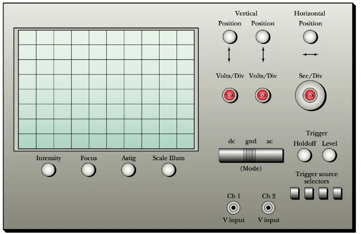
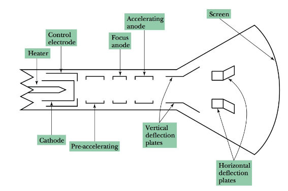
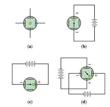
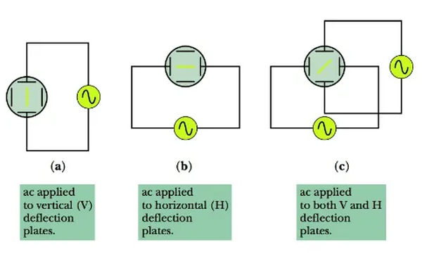
Figure 6a, b, and c show what happens when an alternating current signal is applied to the different deflection plates.
The frequency controls for the horizontal trace of the electron beam across the CRT screen dictate the rate at which the horizontal trace is repeated and its linear trace speed.
Figure 7 shows the result of applying a sawtooth (or ramp-type) waveform to the horizontal deflection plates: a horizontal trace on the screen. Horizontal “sweep voltage” refers to the voltage applied to the horizontal plates, which sweeps the electron beam across the screen in a horizontal direction, producing a horizontal trace or line.
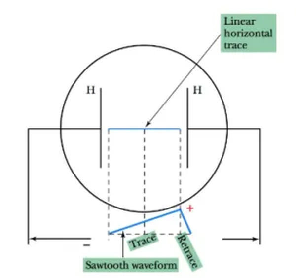
The electron beam “flies” from the left side of the screen to the right side at a constant rate (linear speed), then quickly returns to its initial position on the left. A blanking signal is sent to the system so that the scope screen does not show the movement of the electron beam across the screen (from right to left) during the brief retrace (or fly back) period.
In the left-to-right trace time, a horizontal “time base” is established due to the constant velocity with which the electron beam crosses the screen. We can calculate the amount of time it takes for the beam to travel from one horizontal point on the screen to another. As you will see in a bit, this allows us to take precise measurements of time and to determine the frequency content of displayed signal waveforms.
The frequency of the sweeping (saw tooth) voltage determines how many times per second the beam traces across the screen. If this occurs frequently, a horizontal line will appear on the screen. Because of two factors:
- The material used in CRT screens persists, resulting in the continued emission of light from the screen for a brief period of time after the electron beam has ceased striking that area; and (2)
- Our eyes’ retinas are also equipped with a persistent feature. Because of this, there is no such thing as inter-frame flicker in movies and television.
The sweep frequency of the oscilloscope can be changed using the horizontal time variable, “VAR,” and the horizontal sec/div (seconds per division) controls. A setting here determines how often the beam is moved horizontally across the CRT display. With the help of the horizontal frequency control (or controls), we can observe signals at various frequencies.
With this knowledge in hand, let’s examine how the electron beam is adjusted, amplified, or dampened to produce legible images on the CRT monitor.
The vertical section of the scope is where the signals to be analyzed are introduced, amplified, or attenuated for optimal viewing. In this part, you’ll find the jack(s) for vertical input, also known as a Y input jack, as well as the attenuator(s) and amplifier(s) for vertical signals, along with their respective controls. A single-trace scope has just a single vertical input jack. Each end of a dual-trace scope has two vertical input jacks. (The V input jacks for Figure 3 can be found in Chapters 1 and 2.)
Signals fed into the scope from the vertical input jack can have their amplitude decreased or increased with the help of the vertical attenuator and amplifier circuitry and associated controls (s). Figure 3 shows the controls used to calibrate the vertical sensitivity of the scope, which allows for control over the signal level. You can use these knobs to make the CRT trace vertically deflect more or less for a given amplitude of vertical input signal.
The voltage and signal applied to the deflection plates in the horizontal section can be adjusted. We have skimmed the surface of the many factors and controls that influence horizontal deflection. The horizontal sweep signal, which is generated in-house, can have its frequency changed using one of these knobs.
Aside from the internally generated sweep signal, the horizontal deflection system may also include a jack (typically labeled “Ext X” input) that allows the input of a signal from an external source in place of the internally generated sweep signal.
The signal of interest can be made to appear stationary by using the synchronization controls in conjunction with the horizontal trace (assuming the signal has a periodic waveform). The effect is much like a strobe light that provides “stop action” when timing an automobile, for example. You have probably also noticed that if the light shining on spinning fan blades blinks at just the right rate, the blades will appear to be motionless.
It is not necessary to go into detail regarding the circuitry, but it is sufficient to say that by starting or “triggering” the trace (left-to-right horizontal sweep) of the electron beam in proper time relationship to the signal to be observed on the scope (signal fed to the vertical deflection plates), a stable waveform is displayed.
Controls and jacks associated with this synchronization process include the following:
- Trigger source selector switches
- “Trigger hold off and level” controls, which help set the appropriate level for the triggering signal to work best. (Again, look at Figure 3 to observe these controls.)
Practical Notes
Caution! A common mistake made by novice scope users is leaving a bright spot on the CRT at one location. If this continues for a very long time, the CRT screen material may be burned or damaged. Never have the trace bright enough to cause a “halo” effect on the screen.