The distribution and transmission system is responsible for bringing electricity to commercial and residential buildings. Once electricity is supplied to a building, it is the electrician’s responsibility to route the current to the various outlets and outlets throughout the building.
Switchboard Definition
A switchboard is a large floor-mounted panel or assembly of panels in which electrical switches, OCPDs, buses, and instruments are mounted. See Figure 1. Switchgear is any high-powered electrical device that switches or interrupts devices or circuits in a building distribution system.
In common parlance, switchgear and switchboards are synonymous. Power usually enters a building or property and begins its journey through the building’s power distribution system at the switchboard.
In some cases, the switchboard represents both the end of the utility’s distribution network and the beginning of the building electrician’s network.
The manufacturer places a maximum allowable voltage and current through their switchboards. A switchboard, for instance, might be rated for 50 V with a bus rating of up to 5000 A.
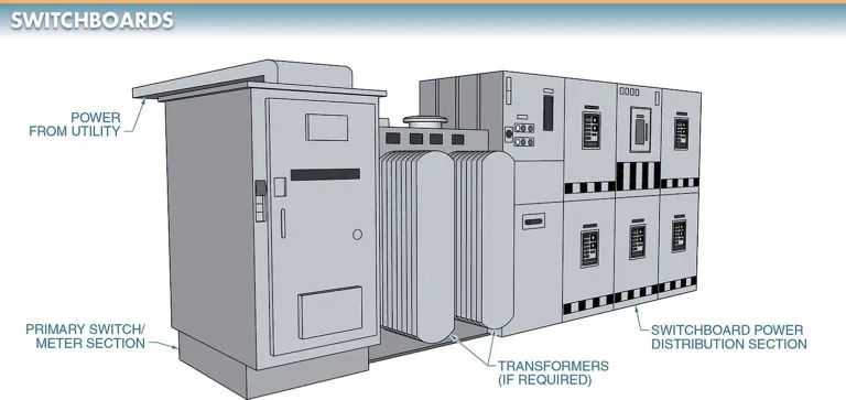
A switchboard is a panel used to distribute electrical power and may also contain devices for managing, monitoring, protecting, and recording the substation’s operations. In the context of service entry and distribution, switchboards shine.
Overcurrent protection, a means to disconnect the service conductors, and metering equipment (if required by the local power company) are all features typically found in a service-entry switchboard. The neutral conductor of the service can be grounded if necessary.
Distribution Switchboard
A distribution switchboard contains the protective devices and feeder circuits required to distribute the power throughout a building. A distribution switchboard may contain either circuit breakers or fused switches.
The local power provider will specify the size and mounting requirements for a distribution switchboard. The purpose of a building’s power distribution system is to provide the necessary voltage and current (DC, 1, or 3) to the loads that are wired into it.
Tenant electricity consumption is measured by meters installed here as well. The switchboard needs a watt-hour meter for metering the incoming power.
Whenever there is a disconnect between two lines, the side with the metering equipment will be the one that receives the power. A sealed cover on the metering equipment compartment ensures that no one can bypass the official metering equipment installed by the utility company. View Figure 2.
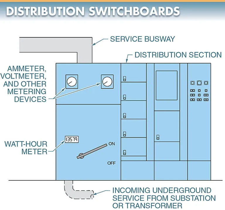
The meter equipment compartment may also feature additional meters and indicator lights. These include voltmeters, ammeters, and wattmeters. Typically, these parts are discretionary depending on the situation and what the plant needs.
The voltages coming into and going out of the building can be seen on a voltmeter by the maintenance staff. A device called an ammeter displays the system’s current levels. The amount of energy consumed by the system is measured by a wattmeter.
These gadgets may function as recorders, indicators, or both. Instruments for recording data are used to keep tabs on variables over time.
A switchboard’s multiple functions include regulating the flow of electricity and monitoring the system’s voltage, current, and power consumption. Switches, fuses, circuit breakers, and overcurrent/overvoltage relays can cut power in the event of an unsafe condition. In the event of a malfunction, these devices safeguard the distribution network.
If your switchboard has more than six individual switches or breakers, you need a master switch to isolate the entire panel.
The main switch is unnecessary for switchboards with seven or fewer switches or circuit breakers. Feeder circuits can increase the rated capacity of the main in a switchboard with more than six switches or breakers by connecting to the main.
It is not uncommon for a single switchboard to house multiple distribution networks. The number of feeder circuits into the building will determine how many outlets the system needs. Article 240 of the NEC® contains further details.
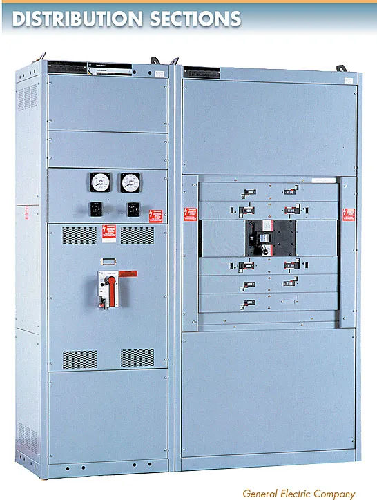
The switchboard’s distribution panel may also have space for motor starters and other control devices in addition to its primary function of power distribution. To see this, please refer to Figure 3.
In order to hook up motors to the switchboard, starters and controls must be installed. When the motors needing control are situated close to the electrical panel, this pairing is a viable option. The combination also enables direct connection of high-current loads, such as motors, to the power source.
Panelboards and Branch Circuits
A panelboard is a wall-mounted distribution cabinet containing a group of overcurrent and short-circuits protective devices for lighting, appliance, or power distribution branch circuits.
Considering that switchboards are typically freestanding, it is easy to tell a wall-mounted panelboard apart from one. Figure 4 is displayed below.
Typically fed by a switchboard, a panelboard further subdivides the power distribution system.
When it comes to protecting the final power feed to the load and its control circuitry, the distribution system’s panelboards are second to none. The function of a panelboard in the power grid determines its category.
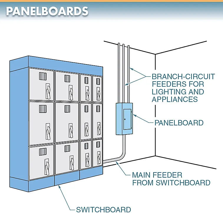
All of the circuits and power-using loads connected to the distribution system are controlled and protected from overcurrent by a panelboard. Observe the fifth figure.
The branch circuits that supply the loads are protected by panelboards, which can be found all over a facility or factory.
The part of the distribution system between the last OCPD and the outlet or load connected to it is called the branch circuit. Panelboards and OCPDs are required to meet the minimum standards outlined in NEC® Articles 240 and 403. Furthermore, one must adhere to all applicable federal, state, and regional laws.
Both fuses and circuit breakers can function as OCPDs, and they are both used to secure branch circuits. Overcurrent protective devices (OCPDs) must have adequate overload and short-circuit protection. If you know the amperage rating of your panelboard and load, you can calculate the appropriate size of your OCPD.
Load breaker protection devices (OCPDs) must not exceed the panelboard’s rating. The panelboard is inadequate for the intended load(s) if the OCPD is higher than the capacity of the busbars in the panelboard.

Figure 5. A panelboard provides the required circuit control and overcurrent protection for all circuits and power-consuming loads connected to the distribution system.
Panelboard Installation
The majority of household circuits inside of a building’s walls start at panelboards. The panelboard’s current and voltage ratings must be adequate, and it must be installed and grounded properly.
The panelboard must be securely installed and grounded to prevent electrical shock and fire. Overloading the system can cause a fire if the panelboard is inadequate.
Panelboards must be installed in accordance with the National Electrical Code® and the National Fire Protection Association’s codes. Switchgear and panelboard installation is addressed in NEC® Articles 403 and 404. Check out the diagram in Figure 6. Workers in the vicinity of panelboards are protected from electrical shocks and fires by these regulations.
Tech Fact
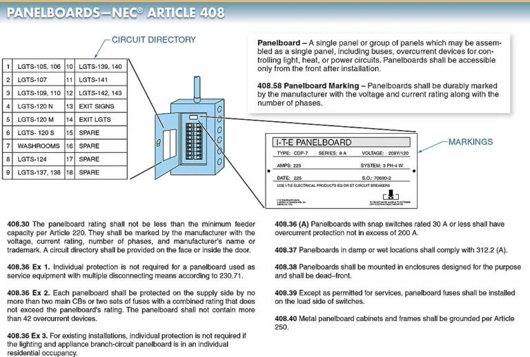
Connecting the main panelboard’s ground bus to the neutral bus with a main bonding jumper creates a ground connection.
The earth grounding system is linked to the ground bus. No other subpanels, outlets, or pieces of machinery should have a connection made from neutral to ground.
A parallel path for the normal return neutral current is created if the neutral is connected to the ground. Because of the potential for electrical shocks, this is an unsafe situation that must be avoided.