Let’s pretend the thick line in Figure 1(a) represents a box that completely encloses the circuit, leaving only terminals A and B accessible. The open-circuit output voltage of the circuit is 80 V as measured by a high-resistance voltmeter connected across these terminals.
The short-circuit current is roughly 2.0 mA when a very low resistance ammeter is connected across terminals A and B. Therefore, it seems that the black box has an internal resistance of

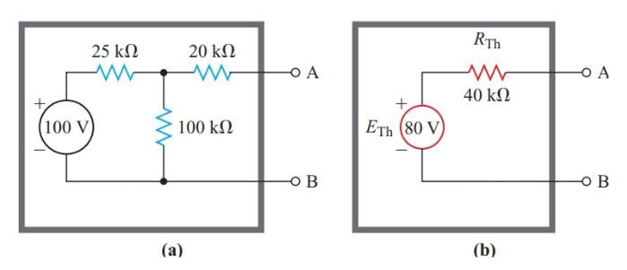
Without breaking the seal, we can see in Figure 1 that the box contains an 80-V power supply (b). If a load is connected to terminals A and B of the equivalent circuit shown in Figure 1(b), it will draw the same amount of current and cause the same amount of voltage drop as if it were connected to the network shown in Figure 1. (a).
Measuring the voltage at the terminals of a circuit with multiple voltage sources tells us nothing more than that the circuit is functionally equivalent to a single internal resistance connected in series with a constant voltage source. Leon Charles Thevenin (1857-1927), a French engineer, formulated a theorem elucidating this correspondence between concepts.
Any two-terminal network of fixed resistances and voltage sources may be replaced by a single voltage source that has
- An equivalent voltage equal to the open-circuit voltage at the terminals of the original network, and
- An internal resistance equal to the resistance looking back into the network from the two terminals with all the voltage sources replaced by their internal resistances.
Thevenin’s theorem can be applied to any resistance network by viewing it as a two-terminal network with one or more voltage sources, and treating one of its branches as a load.
After determining which node in the original network will serve as the load, we cut it off and connect it to a Thevenin-like circuit. After that, we use Thevenin’s theorem to finish up the equivalent circuit.
Take note that Thevenin “looks back into” the open-circuit terminals of the source network with a “ohmmeter” to ascertain the internal resistance.
Thevenin’s Equivalent Circuit Example 1
How much current does the T-network in Figure 1(a) draw when a 10-kV resistor is connected to a 100-V source?
Solution:
Step 1:
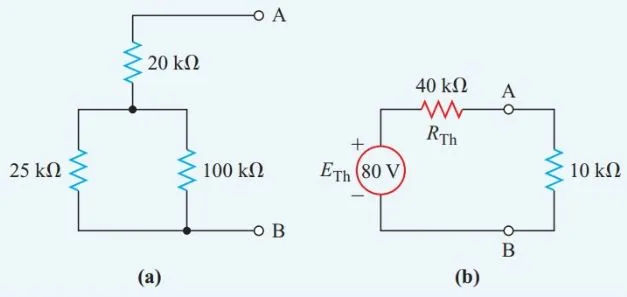
As shown in Figure 2, a Thévenin-equivalent source can be created by connecting the 10-kV resistor to a constant voltage source ETh with an internal series resistance RTh (b).
The open circuit voltage between terminals A and B in Figure 1 is equal to ETh, as predicted by Thevenin’s theorem (a).
Since there is no current in an open circuit, no voltage is dropped across the 20 kilovolt resistor. In this case, the voltage drop across the 100 kilovolt resistor is equal to the voltage at the open circuit terminals.
Resistors of 25 kilovolts (kV) and 100 kV (kilovolts) form a simple series circuit when terminal A is open. Then we can calculate the voltage across the 100 kV resistor using the voltage-divider principle. Open circuit voltage between terminals A and B, or ETh in the Thévenin equivalent circuit, is the source of this drop in potential.

Step 2:
Substitute the source’s internal resistance of zero ohms for the real one in Figure 1(a). Afterwards, the circuit shown in Figure 1(a) transforms into the series-parallel resistance network depicted in Figure 2. (a). For this network, the equivalent resistance is

Step 3:
Figure 2 is a Thevenin-equivalent circuit, so we need to find the current flowing through the 10 kV resistor (b).

Thevenin’s Equivalent Circuit Example 2
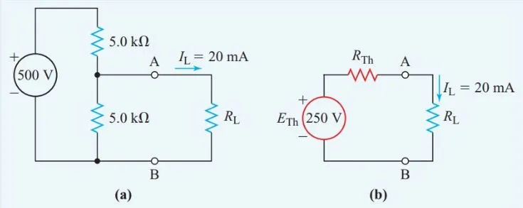
Parallel to a 5.0 kV resistor is a 20 mA current-carrying resistor. This set-up is connected in series with another 5.0 kV resistor and a 500 V supply. To determine the resistor’s resistance, we need to know how much current (20 mA) it is able to carry.
Solution:
Step 1:
Figure 3(b) shows the Thevenin-equivalent circuit after the unknown resistance passing the 20-mA current has been removed from the original circuit in Figure 3(a) (b).
The open-circuit terminal voltage of the remaining circuit in Figure 3(a) is then calculated using the voltage-divider principle:

Step 2:
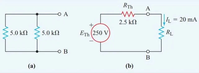
The circuit in Figure 3(a) transforms into the straightforward parallel resistance network in Figure 4(a) once we plug in a new voltage source with an internal resistance of zero ohms.

Thevenin’s Theorem Applications
A circuit’s load may change while all other components remain constant. For instance, the load on a given circuit in the home’s electrical system can be altered by plugging in a variety of devices to different outlets.
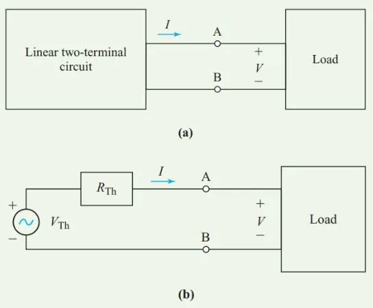
Thevenin’s theorem allows us to replace the unchanged portion of the circuit with a simple equivalent circuit, as shown in Figure 5, simplifying our analysis of circuits with a varying load.
However, Thevenin’s theorem only works for linear inputs (components with values that do not vary with voltage or current).