An electrical circuit device is a component of an electrical or electronic device. There are various types of devices that are used in these circuits. Some of these include switches, sources, connectors, loads, and circuits protection devices. An electric circuit is made up of a device that gives energy to charged particles, such as a generator or a battery. It can also include devices that use a current, such as computers, lamps, and batteries. Some of the basic laws that describe the performance of an electric circuit are the ones known as the Kirchhoff’s and the Ohm’s law.
Many electrical and electronic circuits use the same standard circuit devices. They allow for secure circuit operation by regulating the flow of electrons along the conductor paths. Circuit protection devices, switches, and connectors are covered in this article.
Switches
Installation of switches in circuits allows for regulation of current. Both the actuator and the electrical switching path can be used to classify these devices. The mechanical element that triggers the opening and closing of the circuit is called an actuator.
In Figure 1 you can see examples of a few different switch configurations. Symbols for each switch type commonly used in schematics are also provided.
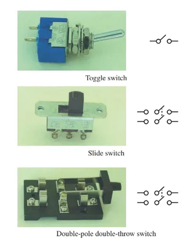
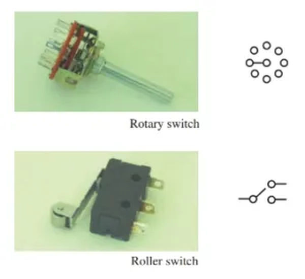
Slide, toggle, rotary, and push-button actuators are all extremely common. The name of the switch itself provides information about the actuator used to activate the circuit.
Poles and throws characterize the internal electrical circuit of the switch. Single-pole single-throw (SPST) switches are the simplest available. As the name implies, a single-pole switch only allows for one direction of electron flow and can be toggled on and off. Single-throw refers to the fact that there is only one circuit that can be altered by flipping the switch.
A single-pole double-throw (SPDT) switch has two independent circuits that can be completed by a single connection point. But remember, you can only complete one circuit at a time. A switch like this has a wide range of configuration options.
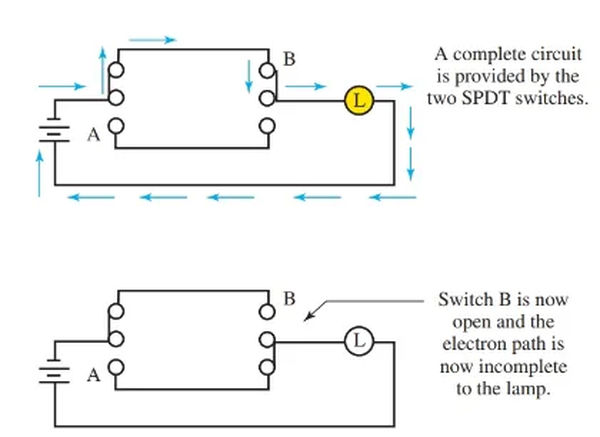
Single-pole double-throw switches are convenient because they allow for dual control of a single load, such as a lamp, from separate locations. The three-way switch is a single-pole double-throw switch used in a home’s electrical circuit.
Two single-pole, double-throw switches control the light in Figure 2. The light can be toggled on and off with either switch.
Since it has two shared terminals, a DPDT switch can offer two independent current paths. Having a DPDT switch is similar to having two SPST switches wired in parallel.
Switch Ratings
The ampacity and voltage ratings of a switch are specified.
The ampacity rating of a switch is an indication of how much current it can safely handle.
The voltage rating is the maximum voltage for which a switch is designed.
If you apply more voltage to the switch than it can safely handle, the internal electrical-mechanical circuitry will break. If a toggle switch is rated for one amp at 24 volts, then any current greater than one amp will damage or destroy the switch’s internal switching circuitry. If the circuit of the 24-volt switch is able to completely block the current. This could cause the switch’s insulation to melt, leading to a dangerous short circuit.
Connectors
Connectors for electrical wires come in a wide variety of styles. The conductor’s size and type, the function of the connection, and the device’s design all play a role in determining the type of connection used.
Check out the illustration in Figure 3. In this book, you will find numerous typical connector varieties. Solder-less connectors are one broad category. No solder is needed for a solder less connector. For the most part, a crimping tool is needed to work with these connectors. The crimping device applies pressure to the connector and the conductor, securing them together. Standard crimps for use on terminals and splices are depicted in Figure 3.
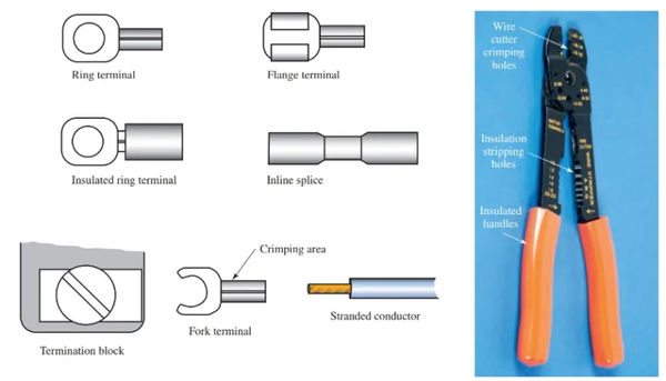
As shown in Figure 3, crimp connectors are designed to be used with stranded wire. The wire can be easily fastened under a termination block screw once the connector has been crimped onto it.
Screws and bolts are used in some connectors to make a mechanical connection to the conductors. Bigger wires call for these connectors, which is why they’re so common. Look at Figure 4.
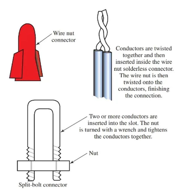
Here we see Figure 4. Wire nut and split-bolt connectors are two examples of solder-free connections. In both domestic and industrial settings, the wire nut is a common fixture. Split-bolt connectors are commonly used on large-diameter conductors.
Circuit Protection Devices
Fuses and breakers are typical circuit protection devices.
Fuse
The fuses in Figure 5 are made of very thin wire. This wire is designed to catch fire at high currents. A fuse’s rating is determined by its ability to handle a certain amount of current and voltage, though the latter is more important.
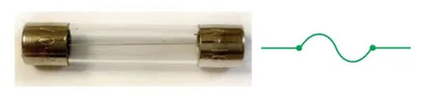
A three-amp fuse, for instance, will melt and break the circuit if the current goes above that level. The fuse link inside the glass tube will melt with a load that draws three amps or more. The amount of overload is inversely proportional to the time it takes to melt the fuse link. Because of this, the melting action accelerates with increasing overload current. A burned-out fuse requires immediate replacement.
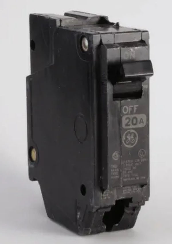
Circuit breaker
Another device used to prevent overload and short circuits is the circuit breaker, also known as a reset. Notice in particular Figure 6.
A circuit breaker’s primary benefit over a fuse link is that it doesn’t have to be replaced when it trips. To turn it back on, just flip the switch to the off position and back to the on position.
A circuit breaker’s actuator may resemble a push button switch on some models. Once the breaker has tripped, it can be reset by pushing it back in. It is necessary to wait for circuit breakers and resets to cool down so that the internal trip mechanism can reset.
Most modern homes have circuit breakers installed as an extra layer of protection against electrical overload. Home fires could result from improper use.
There are two common types of tripping mechanisms used in manufacturing circuit breakers.
Bimetallic strips are used in one such method. A bimetallic strip consists of two distinct metals laminated together. The rate of expansion varies from metal to metal. Due to the excess heat produced by an overload condition, the bimetal trip will enlarge. Metals vary in their rates of expansion. Because of this, the trip mechanism of the breaker is flexed and the circuit is broken. It is possible to fine-tune the trip current with some adjustable mechanisms.
There is an additional mechanism that can be triggered by magnets. A coil is used to direct the flow of electricity in the circuit. More magnetism is created in the coil as the current flows through it. The tripping mechanism activates and the circuit opens when the setpoint is reached.
In comparison to its bimetallic counterpart, the magnetic circuit breaker is noticeably quicker and more precise. However, the magnetic circuit breaker is more costly than its bimetallic counterpart.