Overload protection for the motor is built into solid-state motor starters, which are electronic switches (contactors) that don’t use traditional mechanical switches. After the disconnect/overcurrent protection device and before the motor, solid-state motor starters are wired into the circuit.
In the same way that pushbuttons, pressure switches, and other controls can activate electromechanical motor starters, so can solid-state motor starters. Refer to Figure 1.
The conducting states of solid-state components like SCRs or triacs in a solid-state motor starter allow current to flow and shut off current flow, respectively.
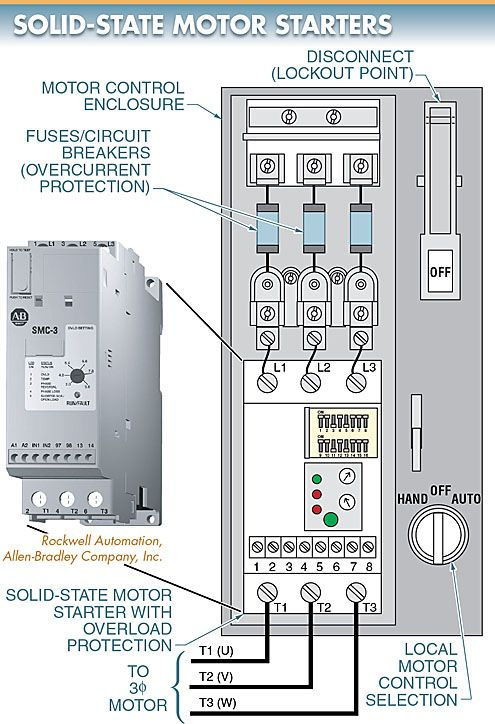
Solid-State Motor Starter Components
A solid-state motor starter will have terminals labeled L1, R2, S3, and T3 for connecting the incoming power supply and T1, U, V, and W for connecting the motor. The terminal strip on solid-state motor starters allows for the connection of various optional inputs (pushbuttons, proximity switches, etc.).
In addition to the potentiometers used to modify the motor’s full-load current (in amps) and trip class, solid-state motor starters feature a dual inline package (DIP) switchboard for programming starter functions (starting mode/time, stopping mode, etc.). LEDs can be used in solid-state motor starters to show the user the status of the circuit. Observe the second figure.
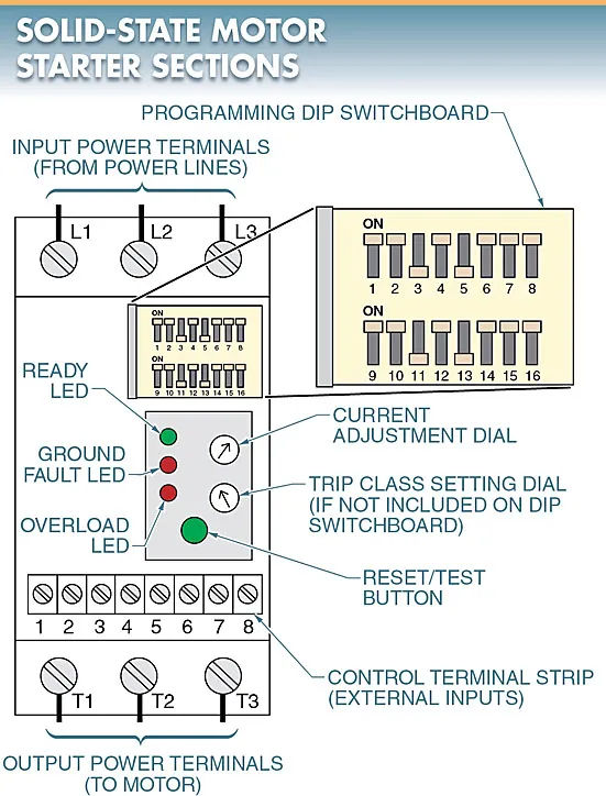
Wiring Power and Control Circuits
A solid-state motor starter’s power circuit is wired so that it receives power from the fuses or circuit breaker. The voltage coming into the motor must match the voltage that the motor is rated for or wired to. A look at Figure 3 is in order.
The starter’s control terminal strip is where the control circuit connects. The power supply voltage is higher than the control circuit voltage (typically 12 VDC, 12 VAC, 24 VDC, or 24 VAC).
An external control voltage input, external control switches (pushbuttons, temperature switches, etc.), and output contacts (alarms, indicating lamps, etc.) are all included on the control terminal strip.
Setting Overload Protection
Motors need safeguards against overloads and excessive currents. For overcurrent protection, a motor can have fuses or circuit breakers installed (typically in the motor disconnect) (short circuits and high operating currents).
The overloads in the motor starter prevent damage to the motor from the excessive current that occurs when the load on the motor exceeds the motor’s rated torque. In addition to thermal overloads (heaters), solid-state overloads are also available.
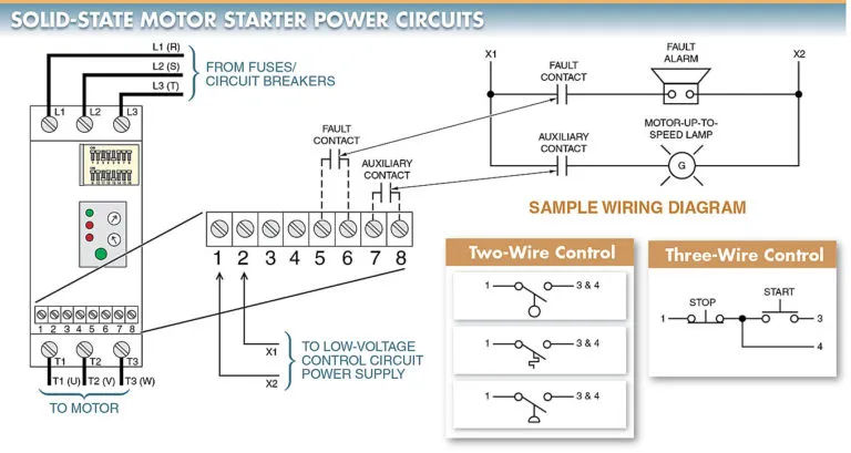
Figure 3 shows how a solid-state motor starter is wired, with power entering the starter from the fuses or circuit breaker. The starter’s control terminal strip is where the control circuit connects.
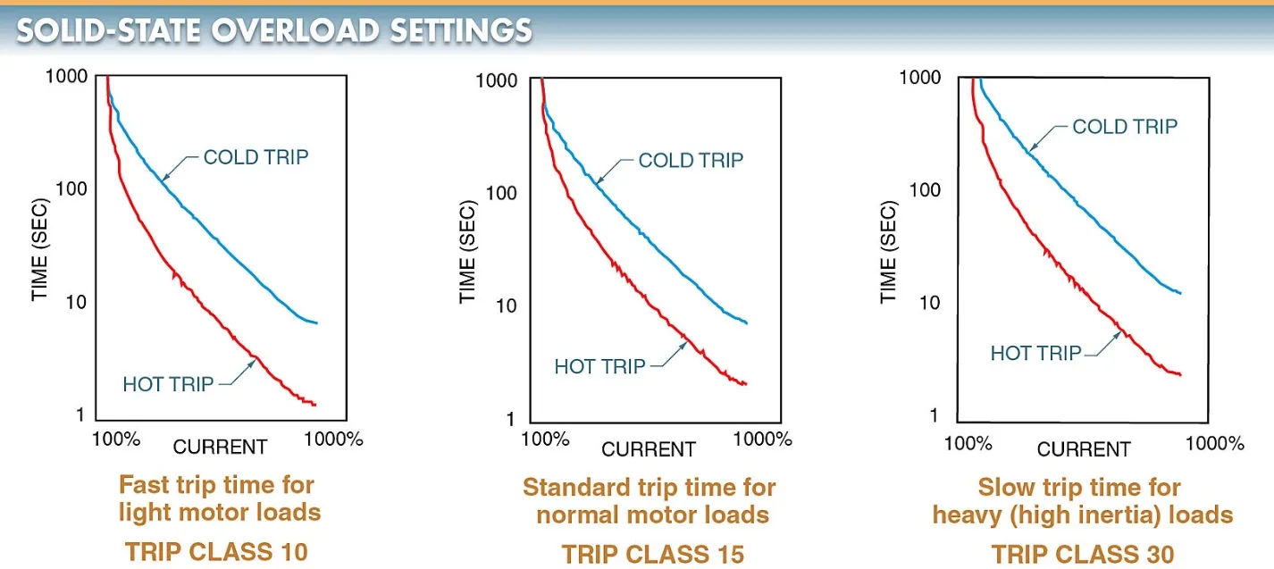
The trip class setting is the length of time it takes for an overload relay to trip and remove power from the motor.
In order to keep track of each individual power line, solid-state overloads employ a current transformer (CT). The current limit of a solid-state overload is determined by the motor’s nameplate full-load current rating and the trip class (class 10, 15, 20, or 30). The starter features a current adjustment dial used to set the current limit.
The solid-state overload’s trip time decreases as the trip class decreases. When the trip class is increased, the solid-state overload does not trip as quickly. It is the motor’s intended use that determines the trip class (a type of load placed on the motor). There is a dial next to the current adjustment dial where the trip class setting can be changed, or you can use the DIP switches. Notice in particular Figure 4.
When the motor is first started, the cold trip occurs, and the overloads trip for the first time (motor operating below nameplate rated current). Once the overloads have tripped and been reset, that’s when you’ll reach the “hot trip” point (motor operating near or over nameplate rated current).
Tech Fact
In most cases, a class 20 trip rating is used for magnetic motor starter overloads. Class 10 trip rating is typical for solid-state starters and drives. Selecting a lower class number, or fast/minimum or slow/maximum if no class numbers are available, will typically set a slower trip time.
Solid-State Starting
Unlike across-the-line starters, which apply full voltage all at once to the motor, a solid-state reduced-voltage starter gradually increases the voltage to the motor as the motor speeds up. When compared to the high inrush current generated by across-the-line starters, the inrush current of solid-state starters is significantly lower.
Even though some loads attached to the motor can be damaged by excessive starting torque, the acceleration of the motor is smooth when using a solid-state starter. Refer to Figure 5.
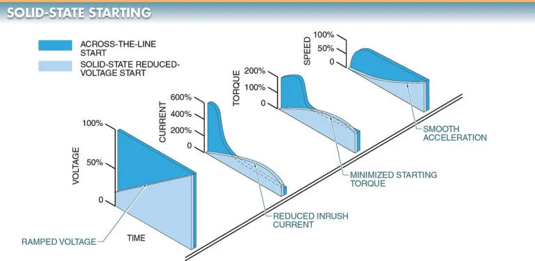
When starting conveyors, compressors, pumps, and many other industrial applications, solid-state starting is preferred because of its unique switching capability, which allows for a smooth, stepless acceleration.
Electronic Control Circuitry
A solid-state controller decides when and how much to turn on SCRs, which in turn regulates the voltage, current, and torque delivered to the motor.
Protective components of a solid-state controller include current-limiting fuses and current transformers. To prevent damage to the SCRs from excessive current, limiting fuses are installed. Information is relayed to the controller via the current transformers. To further prevent damage from excessive heat, heat sinks and thermostat switches are also used to shield SCRs.
Furthermore, the controller provides the sequential logic required to interface with the starter’s other control functions, such as the detection of line loss during acceleration. If power is lost or drops too low on any given line, the controller shuts down. If a fuse or line breaks, this could occur.
Solid-State Starting Circuits
When using a solid-state starter, it is common to connect the start and run contactors together. The contacts C1 of the start contactor are connected in series with the SCRs, while the contacts C2 of the run contactor are connected in parallel. For more information, please refer to Figure 6.
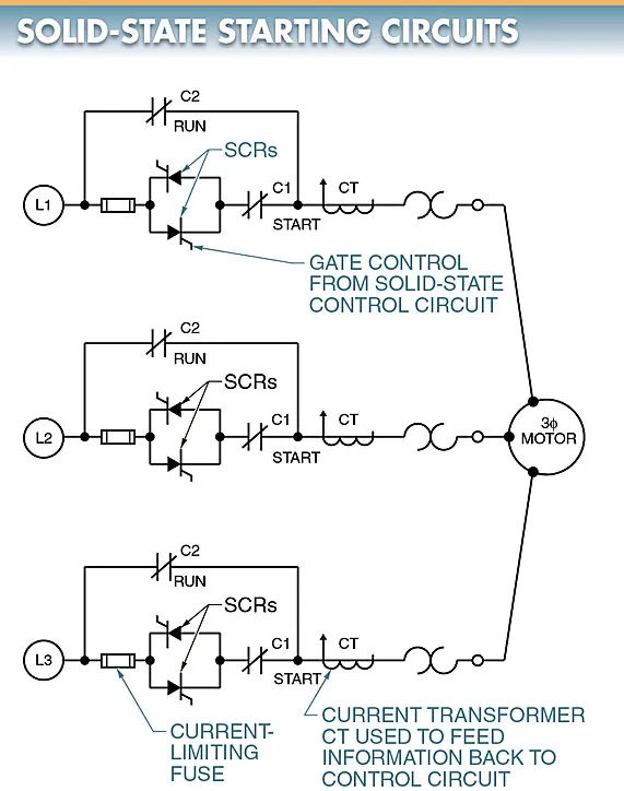
SCRs are triggered on when the starter is energized, closing the start contacts C1, and regulating the motor’s acceleration. Until the motor reaches full speed, the SCRs regulate it, and then the run contacts C2 close, connecting the motor directly across the power line. At this point, the SCRs are disabled and full current is supplied to the motor.
Motor Starting Modes
Electric motors can be kicked into gear with either an electromechanical or a solid-state starter. The motor is connected to the full supply voltage when an electromechanical motor starter is used.
When a motor is supplied with its maximum voltage, it draws its maximum current, applies its maximum torque to the load, and accelerates to its maximum speed in the shortest time possible. For some loads, this level of operation might be fine. Light loads (small parts, etc.) and delicate loads mean that they cannot be started with a high starting torque (paper rolls, etc.).
Power distribution system breakers and fuses can be damaged by excessive starting current. Programmable solid-state motor starters have multiple starting modes that can be used to mitigate issues brought on by full-voltage starts.
Motor starting modes include soft start, soft start with start boost, and current-limit start. See Figure 7.
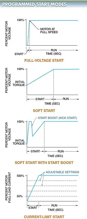
As shown in Figure 7, solid-state motor starters can be adjusted to operate in a variety of starting modes to mitigate issues associated with full-voltage starting.
Soft Start
The most common kind of solid-state starter is the soft start. A soft start is a feature of some starters that gradually speeds up the motor over a predetermined amount of time, typically between zero and thirty seconds.
Starting times of 2 seconds, 4 seconds, 6 seconds, 8 seconds, and 16 seconds are all fairly common. Starting torque can be set as a percentage of locked rotor torque. A 15%, 25%, 50%, or 60% torque setting is typical for a start. Through the use of a soft start, the motor and any attached loads are subjected to less initial stress.
The ramp-up control increases the voltage to the motor gradually, allowing for a gentle start. Time spent ramping up can be adjusted with a potentiometer (normally 1 sec to 20 sec). Using the ramp-down control’s preset value, the motor’s voltage is gradually reduced to bring about a soft stop.
The ramp-down time is adjusted by a second potentiometer (normally 1 sec to 20 sec). To get the motor to spin immediately when soft starting is used, the voltage applied to the motor must be set using a third potentiometer. Refer to Fig. 8.
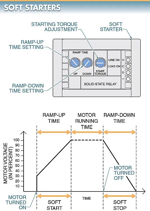
Figure 8 depicts a soft starter, which is a device that gradually increases voltage (ramps up) when starting a motor and gradually decreases voltage (ramps down) when stopping the motor.
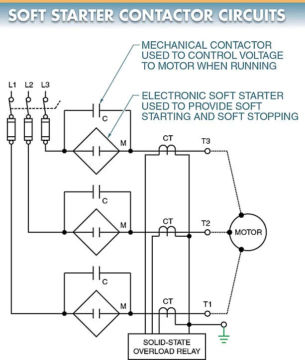
The heat generated by a soft starter, like that of any solid-state switch, must be dissipated for the device to function properly. Controlling high-current loads (motors) necessitates the use of sizable heat sinks. Due to this, a contractor is frequently installed alongside a soft starter.
The motor’s starting and stopping processes are managed by the soft starter. When the motor is operating, the contactor closes to prevent current from flowing through the soft starter. This means that large heat sinks are not required to achieve soft starting and soft stopping when the motor is in operation. The soft starter has a signal that can be used to turn the contactor on and off at predetermined intervals. The example is shown in Figure 9.
Soft Start with Start Boost
For loads that are particularly challenging to get going, a solid-state motor starter can be programmed for soft start with start boost, which sends a current pulse to the motor at the beginning of the starting process.
Typically, the boost time can be altered from 0 seconds up to a maximum of 2 seconds. When soft starting the motor fails, the start boost is used to get the motor going.
Programming Solid-State Motor Starters
Before turning on the power, a solid-state motor starter needs to be programmed for correct operation. Each DIP switch on a solid-state motor starter is programmed to a specific setting that corresponds to the needs of the motor and the application.
Some DIP switches have only four or six settings, while others have dozens. When more settings are accessible, the starter can be used in a wider variety of situations. Refer to Figure 10.
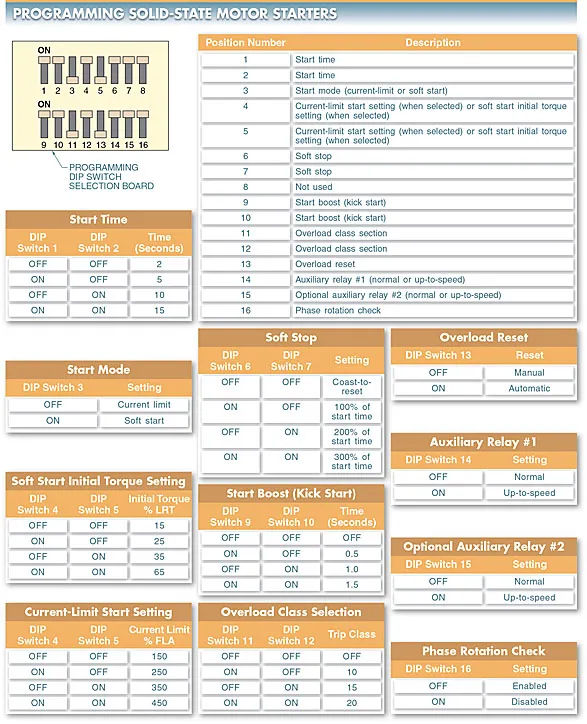
Motor starting mode (start time, soft start, start boost, etc.) and auxiliary contact operation are some of the parameters that can be set with a DIP switch (when they are open or closed).
Some DIP switch settings may be critical to safeguarding workers, the motor, and the system, so it’s important to familiarize yourself with them all before turning on the starter.
Overload reset, for instance, has both manual and automatic settings. For manual restarts, the starter must be turned off and the motor reset (by external pushbuttons, etc.).
In automatic reset mode, however, if the external control switch (pressure switch, etc.) is still closed after a set amount of time, the starter will restart the motor on its own. If the person working on or near the system is unaware that the motor may restart on its own, it poses a safety risk. When in doubt about what a given DIP switch setting actually means, it’s best to check the manual provided by the device’s manufacturer.
Motor Stopping Modes
Electric motors can be turned off using either an electromechanical or solid-state starter. Any load on the motor will affect how quickly the motor will coast to a stop when using an electromechanical starter.
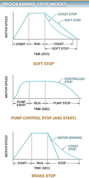
Different modes of stopping are available for use with solid-state motor starters. Because of this, the motor/load can be protected in a wider variety of situations. The motor has several different types of shutdown, including a soft stop, pump control, and brake stop. For an example of this, please refer to Figure 11.
Soft Stop
Most solid-state motor starters utilize a soft stop as their primary stopping method. In contrast to hard stops, soft stops allow for a more gradual and controlled stop. Deceleration time in a soft stop is determined by the starter and not the load. With the soft stop mode, the motor will not abruptly stop when the load’s friction is removed.
Pump Control
Whenever a centrifugal pump is started or stopped, it causes a surge that can be mitigated by switching to the pump control mode. Motors and pumps can be started and stopped gradually or with a smooth acceleration and deceleration using the pump control mode.
Starting times for motors and pumps typically take between a few seconds and thirty seconds. Standard shut-off times for motors and pumps typically last anywhere from a few seconds to one minute and twenty seconds.
Brake Stop
Sometimes, you need to shut off the motor quickly. When engaged, the brake stop mode uses motor braking to bring the vehicle to a stop more quickly than the coast stop or soft stop. The amount of braking (and hence the amount of time spent braking) is determined by the needs of the application. When in brake stop mode, the maximum time is initially set, then reduced as necessary.