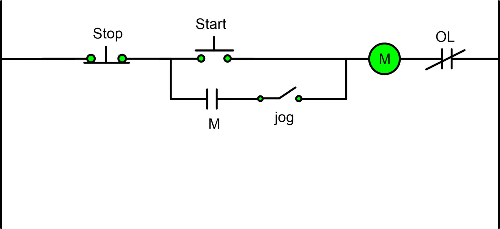
If you want to make a circuit where the operator can briefly power it on without pressing the stop button, you’ll need a jog circuit. Jog circuits enable the operator to move loads to a predetermined position without causing the load to overtravel.
Since the jog circuit only requires momentary energizing and de-energizing of the pilot device, it can be implemented in nearly any control circuit.
What is jogging in motor control
Jogging or inching is defined as the quickly repeated closure of a circuit to start a motor from rest for the purpose of accomplishing small movements of rotating machine.
When starting a load at full voltage, the term jogging is commonly used, while when starting at a lower voltage, the term inching is more commonly used. Because they both serve to thwart the use of a seal-in circuit, the terms are often used interchangeably.
The design of a jog control circuit can take many forms. When planning a jog, keep in mind that the ultimate goal is to have a load run for the entire time the start button is depressed. This means the control circuit is built in such a way that the memory/seal-in contact cannot energize the load and keep it that way.
Start Stop Jog Motor Control Diagram
A two-circuit pushbutton is one implementation of the jog circuit. If you use the circuit’s start and stop buttons, it will function like any other three-wire circuit. When the jog switch is pressed, a connection is made between the control circuit and the load. One risk, however, is that the jog button could become the active seal-in, keeping the load on even when no one is pressing the button. If it is possible to do without the use of pushbuttons that both make and break the control circuit in the same circuit, that would be ideal.

Configuration 1 Jog circuit operation is as follows:
- An on/off switch is connected in series with the pilot device’s sealing circuit.
- When the switch is closed, power is connected to the push button’s start and seal-in terminals, and the control circuit operates as though it were a conventional stop/start station controlling a load connected to the pilot device.
- With a single press of the start button, the coil is instantly energized via the start pushbutton and the seal-in contacting.
- The start pushbutton is no longer required because power is constantly being supplied to the coil via the seal-in contact.
- There are a few options for turning off the power to the motor starter’s coil.
- The motor’s normally closed overload contacts may open if it experiences an overload, effectively breaking the circuit.
- By pressing the stop button, current is cut off at the seal-in contact, de-energizing the coil.
- The jog position of the switch is the next possible means of interrupting the control circuit. In an instant, the coil’s energy will be cut off.
- After moving the toggle to the jog position, the pilot device will no longer receive power via the seal-in contact.
- Only by pressing the start button for a set amount of time is the coil energized.