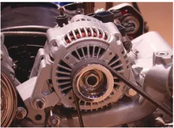
Essentially, an alternator is a device that converts mechanical energy, like the rotation of the alternator pulley, into electrical energy.
What makes up a standard alternator in particular are:
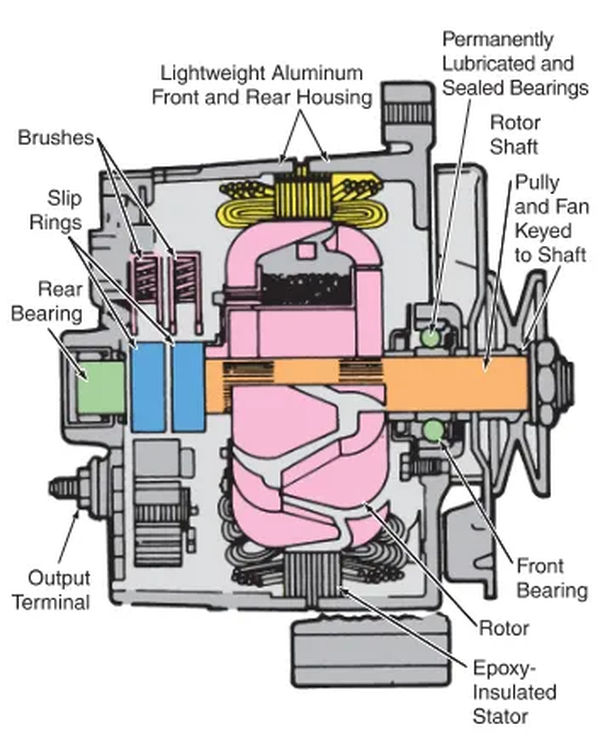
- Rotor assembly—field windings, claw poles, rotor shaft, and slip rings.
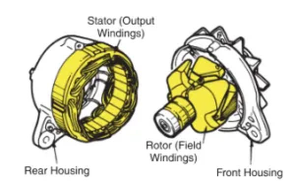
- Stator assembly—three stator windings, stator core, and output wires.
- Brush assembly—brush housing, brushes, brush springs, and brush wires.
- Rectifier assembly—diodes, heat sink or diode plate, and electric terminals.
- Fan and pulley assembly—fan, spacer, pulley, lock washer, and pulley nut.
- Housing—drive end frame, slip ring end frame, and end bolts.
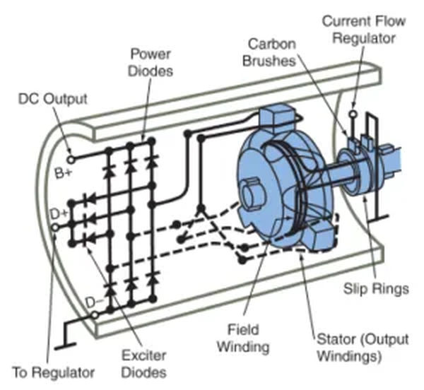
As shown in Figure 2, the alternator generates alternating current that is rectified into direct current for use by the car’s electrical components.
Rotor and Stator Assemblies
The rotor and the stator are the two primary components of a basic alternator. Look at Figure 4. As can be seen in Figure 5, the rotor consists of a magnetic field winding attached to a shaft. So that it can spin freely, the rotor shaft is supported by roller or needle bearings. When the rotor is turned by the alternator belt, the field begins to rotate.
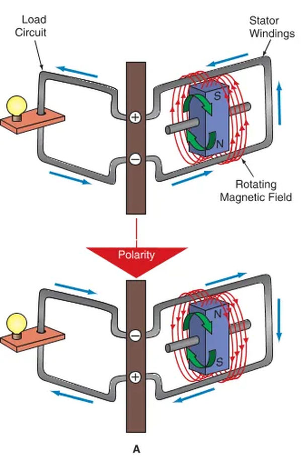
A—Current is induced in the stator’s stalwart windings by the revolving magnetic field.
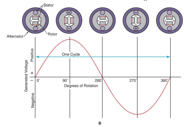
B—An output current is created as the north and south poles of the rotating field cut across the fixed windings. When the current flows in the opposite direction, as in a sine wave, the polarity flips.
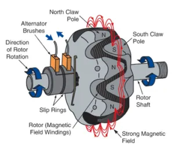
Figure 5. The rotor has claw poles that surround its windings. This produces a strong magnetic field that induces current into the stator. Note the north and south poles of the claws.
Grease is commonly used to pack the bearings in an alternator. A small plate and screws are commonly used to secure the front bearing. It is common practice to press-fit the rear bearing into the axle.
The rotor is the moving part of an electric motor, and the stator is the stationary windings that surround it. Notice in particular Figure 6. The alternator’s output winding is housed in the stator. Figure 7 depicts the typical configuration of a rotor and stator. An electric current is induced in the stator windings by the rotor’s sharp magnetic field as it spins. A load will be powered if connected to the stator windings.
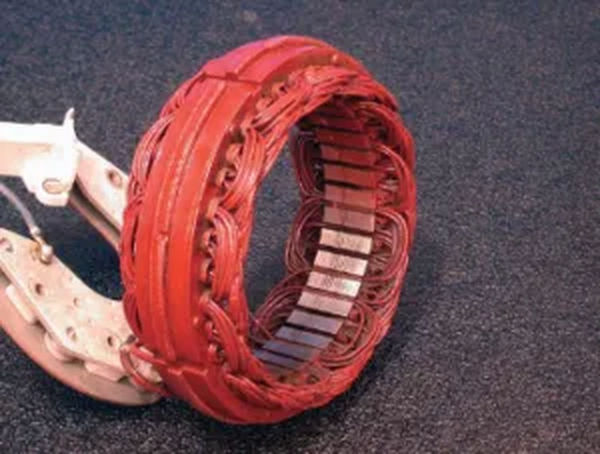
Typically, the stator has three coils wound around an iron core. Because of the iron core’s contribution to a more powerful field, the rotor is able to induce a greater current into the stator.
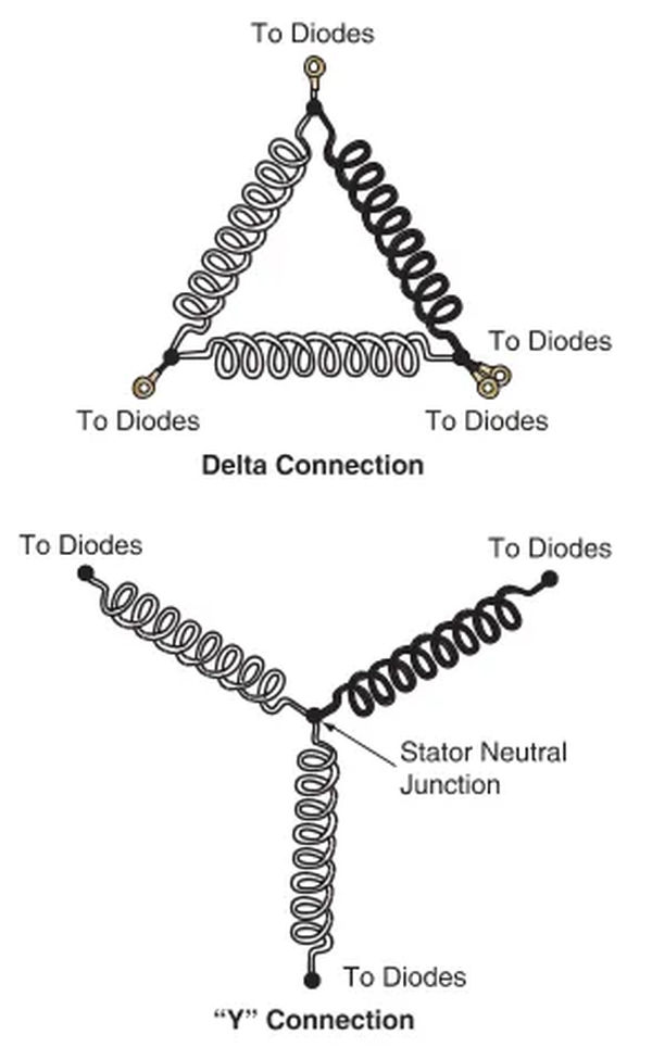
In Figure 8 we see two distinct stators. The stator windings’ bare ends are connected to a neutral junction in a Y-type stator, forming a circuit in the shape of the letter “Y.” At low engine speeds, the Y-type stator’s high current output is particularly useful. Stator wires in a delta configuration are joined together at each terminal. Each phase, or AC voltage output from the alternator, creates two circuit paths between the diodes because there is no neutral junction. The high-output alternators typically use delta-type stators.
Brush Assembly
The alternator’s brushes slide across slip rings to make a contact for the electrical current. Look at Figure 9. The slip rings are installed on the rotor shaft and supply the rotor windings with a minimal current. Recall Figure 5 for further clarification. The field winding is joined at both ends by means of slip rings. To generate a magnetic field, the field windings must be excited by an external source of electricity.
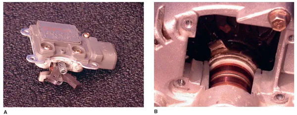
A—The housing for the voltage regulator contains these alternator brushes. The regulator and brushes are a unit that is bolted onto the back of the alternator case.
B—The slip rings on the rotor assembly are visible when the brush-regulator assembly is taken apart. To make a rotating electrical connection to the rotor windings, the brushes slide along the slip rings.
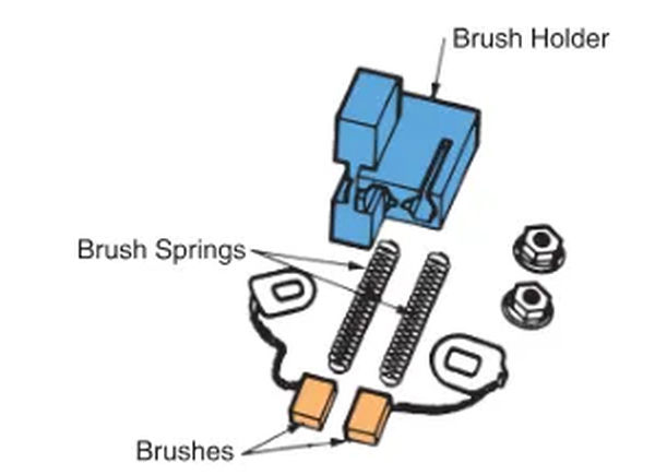
The brushes are pushed into contact with the slip rings by tiny springs. Due to the low current flowing through the rotor windings, these brushes can be much smaller than motor brushes. 10 See Figure.
The brush springs and individual brushes are contained within the brush holder. It maintains proper brush-to-rotor-slip-ring alignment. To avoid accidental brush grounding, the holder is made of an insulating material.
Rectifier Assembly
Direct current, which can only flow in one direction, is ideal for an automobile’s electrical system. Unfortunately, the alternating current that is produced by the alternator stator is not suitable for use in this device. The alternating current from an alternator must be rectified (converted to direct current) before it can be used.
The stator output is sent through a string of diodes to achieve this result. Complete rectification of the stator AC is shown in Figure 11 by the use of six diodes.
The diodes inside an alternator are typically wired as shown in Figure 12. Take note of the diode circuit’s connection to the stator leads. The diodes’ output is wired to the alternator’s external terminals.
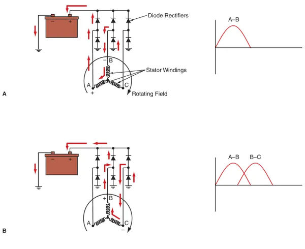
You can see these diodes in Figure 11. They are used to change alternating current into direct current. When the rotor is spinning, only a pair of diodes and a pair of stator windings are on.
A—Windings A and B form a series circuit and are thus active. A current is generated in winding A, passes through one diode, and then reaches the battery’s positive terminal. One diode completes the circuit back to winding B.
B – Current travels from winding B, through a single diode, and into the battery’s positive terminal. Through one diode, the current is sent back to winding C.
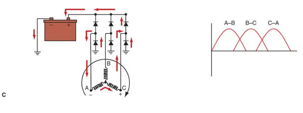
C – Winding C is the source of the current that travels to the positive battery terminal via one diode. One diode carries the signal back to winding A.
Fan and Pulley Assembly
A fan is installed in front of the rotor shaft to cool the alternator. Its typical position is in front of the pulley. The fan aids in cooling the alternator by directing airflow over and through it as the rotor and shaft rotate. By doing so, the windings are protected from overheating.
The alternator pulley is mounted on the front of the rotor shaft with a large nut, and the alternator belt travels from the crank pulley to it. The rotor is rotated by the belt that connects the crankshaft to the alternator. You can use a ribbed belt, a V-belt, or a cogged V-belt.