Electrical energy can be transformed into linear mechanical force by means of a solenoid, an electric output device. A solenoid’s magnetic attraction could be harnessed to transfer energy. An armature can be used in conjunction with a solenoid to convert the force generated by the solenoid into mechanical work. The part of a solenoid that can be moved is called the armature.
Solenoid Types
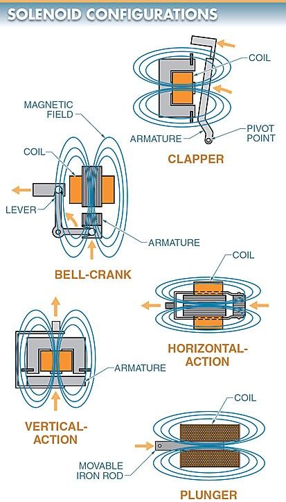
The shape and size of solenoids can be adjusted to suit a wide range of uses and performance parameters. There are five different types of solenoids: the clapper, bell-crank, horizontal-action, vertical-action, and plunger. Refer to Figure 1.

The armature of a clapper solenoid is mounted on a pivot. The armature is captured when it is in its closed position, which is achieved as voltage is applied to the coil and a magnetic effect is produced (sealed in).
In a bell-crank solenoid, the armature’s vertical motion is converted to a horizontal one by means of a lever connected to the armature. A lever is used so that the armature’s shock is absorbed by the lever rather than being transferred to the end of the lever. When operating the controls, this is helpful when a gentle but firm touch is needed.
An example of a direct-action device is a horizontal-action solenoid. The resulting force travels in a straight line due to the armature’s motion. One of the most common solenoid configurations is the horizontal-action solenoid.
A vertical-action solenoid, like a horizontal-action solenoid, has a mechanical assembly, but the armature’s vertical motion is transmitted in a linear fashion.
A plunger solenoid is made up of a single iron cylinder (or rod) that can be moved up and down. An iron rod can be moved around inside the coil, and when electricity flows through it, the rod will seek to find its “center of gravity,” so to speak. If the rod and solenoid are the same length, the current will pull the rod to the center, where its ends will meet.
The rod in a plunger solenoid is displaced slightly from its axial position in the coil by means of a spring. When the current is turned on, the rod moves in the opposite direction of the spring tension in order to re-center itself in the coil. When the power is cut, the spring resets the rod to its original, non-centrifuged position. It’s possible to use the rod’s motion to power a wide variety of mechanical implements. Figure 2.

Figure 2. In a plunger solenoid, a spring is used to move the rod a short distance from its center in the coil. The rod moves against the spring tension to re-center itself when the current is turned on.
Solenoid Construction
Solenoids consist of a magnetic laminate assembly wrapped in many turns of wire. When electricity is run through the coil, it pulls the armature in toward it. The solenoid can have devices attached to it to do things like open and close contacts.
Eddy Current
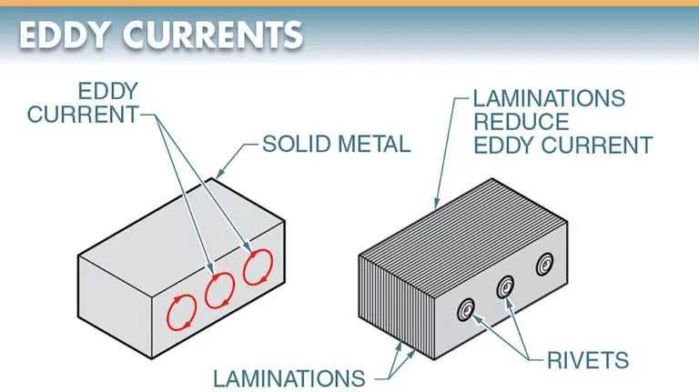
As the rate of change of the induced magnetic field increases, eddy current is induced in the metal structure of the device. When alternating current is applied to a solid metal, it creates powerful eddy currents.
The armature and magnetic assembly of AC solenoids are made of many thin metal sheets laminated together. The eddy current created in the metal is mitigated by the thin metal strips. Notice in particular Figure 3. Because eddy current is localized within each lamination, the magnetic effect and associated heat are mitigated.
Since DC solenoids only use a continuous, one-way current, a solid core is fine for them.

Armature Air Gap
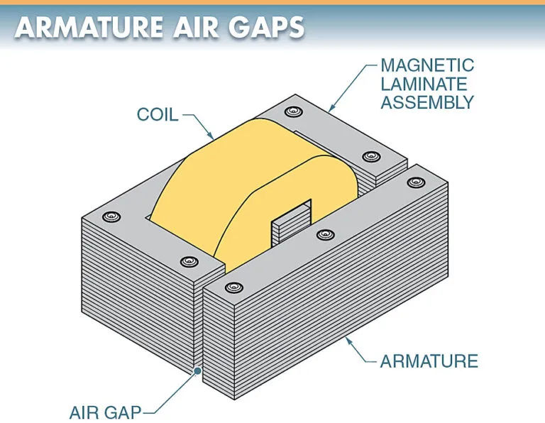
Solenoid armatures are magnetically attracted to their sealed-in positions to maximize the efficiency of the magnetic circuit and minimize chattering. For this purpose, the armature and magnetic laminate assembly are machined to an extremely tight tolerance.
Some magnetic lines of force (residual magnetism) are always retained after the coil is de-energized, and this may be enough to keep the armature in the sealed position. In order to prevent this from happening, a small air gap is always left between the armature and the magnetic laminate assembly. This breaks the magnetic field and lets the armature fall freely when the motor is turned off. Figure 4.

Shading Coil
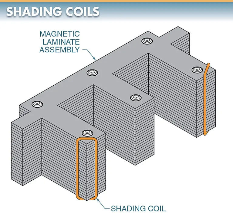
The magnetic laminate assembly or armature’s face may be outfitted with a single shading coil, which consists of a single turn of conducting material (typically copper or aluminum). Refer to Figure 5. When the magnetic field of the main coil in an alternating current circuit decreases to zero, a shading coil creates a secondary magnetic field to keep the armature from moving.

Periodically, the magnetic field created by alternating current vanishes entirely. The armature will drop out or chatter as a result of this. The armature is held firmly in place by the unit’s magnets and the additional pull provided by the shading coil. The life expectancy of the armature is shortened because of the excess noise, wear, and heat that builds up on the armature faces when the shading coil is not present.