A series circuit is an electrical device that only has one path for the current to flow through. If a user follows a series circuit from one end of the board to the other, all of its components will be connected without any branches. If a break or disconnection occurs, all of the components in the circuit will fail.
Either the connection between components or the current through them can be used to identify a series circuit.
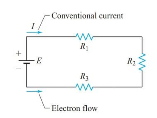
To illustrate, in Figure 1, R1 and R2 are connected in series because there is no other component or branch connected to the junction of R1 and R2. All the components are connected in series because there is no parallel branch at any of the circuit’s junctions. Therefore, current can only flow in one direction in a series circuit.
Since resistors cannot store charge, the current passing through R1 is the same as the current passing through R2, and so on.
As with any other part of the series circuit, the source has the same effect on the current as any other link. As far as we know, Georg Ohm was the first to notice this crucial aspect of series circuits.
In a simple series circuit, each component receives the same amount of current. In contrast, if a shared current flows through two or more electric components, then they are said to be connected in series.
It is not necessary to use a subscript with I to differentiate the current through the various components in a series circuit because the current is shared by all of them.
I in Figure 1 stands for the total current flowing through R1, R2, and R3 as well as the source and the connecting wires.
Let’s pretend that Nichrome wire is used to construct resistors of different values: R1 has 2 m, R2 has 1 m, and R3 has 3 m.
A Nichrome wire measuring 6 meters in length is used to conduct electrons through the circuit. The total resistance of this circuit is the sum of the individual resistances because the resistance of an electric conductor is proportional to its length. Generalizing,
Each element’s resistance adds up to the total resistance in a series circuit.

A series circuit’s common current can be calculated using Ohm’s law once its total resistance has been determined.
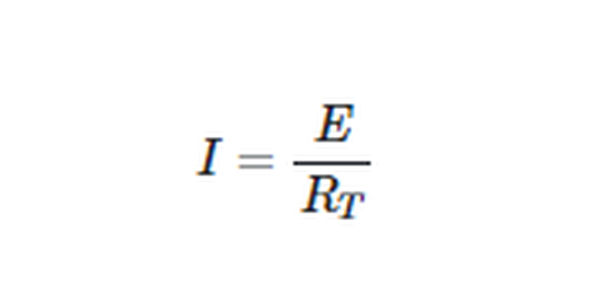
The applied voltage E causes a voltage drop of this current, which is denoted by VT. Because of this, the voltage drops across all of the resistors are also equivalent.
Series Circuit Example 1
Determine the amount of current that will flow through a series circuit made up of a 45- source, a 20- resistor, a 10- resistor, and a 30- resistor.
Solution

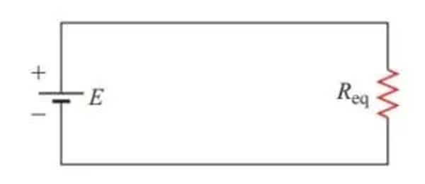
A single 60-V resistor connected to the source’s terminals draws the same current as three 10-V, 20-V, and 30-V resistors in series. Since this is the case, we can replace the series resistances with the equivalent resistance Req.
The equivalent circuit for the series circuit shown in Figure 1 is depicted in Figure 2. When performing analysis on more complex circuits, it is common practice to eliminate unnecessary complexity by replacing multiple components in series with a single equivalent component.
Voltage Drops in Series Circuits
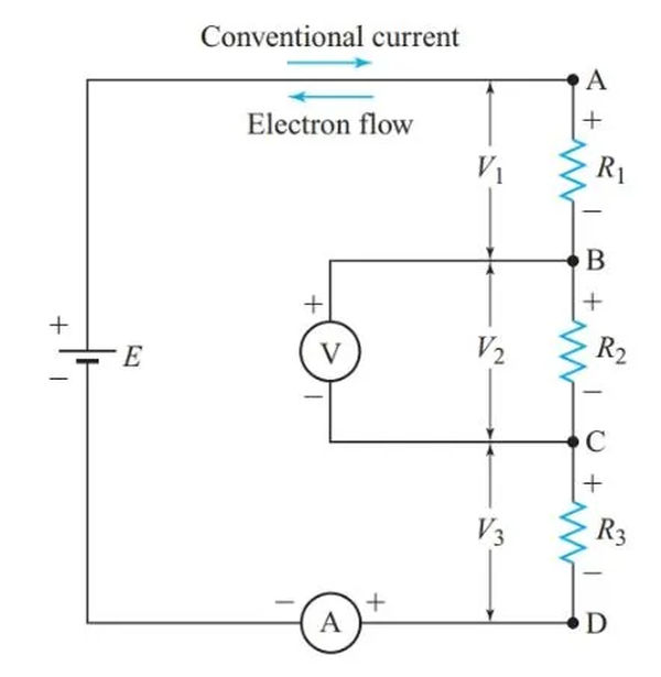
The voltmeter and ammeter from Figure 1 have been added to the simple series circuit in Figure 3. The components are connected in the same way as in Figure 1, but R1 and R3 are in different places.
In order to measure the current in a circuit, an ammeter must be connected in series with the circuit.
The voltmeter’s connection to points B and C allows it to read the voltage difference across R2. The ideal voltmeter has a very low current draw and will have a very small impact on the circuit.
As shown in Figure 3, the voltage source uses energy to move electrons from the positive terminal to the negative terminal, raising the potential of the electrons inside the voltage source.
The electrons’ potential energy decreases as they leave the source and move through the external circuit. Therefore, electrons at point D have a higher potential than electrons at point C, and electrons at point B have a higher potential than electrons at point A.
Similarly, the electrons at point B have a lower potential than those at point C, and so on.
As with electrons, negative ions in the voltage source will move in the same direction if they are not restricted. Positve charge carriers travel in the opposite direction. When electrons with a positive charge move from the negative to the positive terminal of a voltage source, the potential of those electrons increases.
Since it creates electrical energy, a voltage source is considered a “active” component of a circuit (at the expense of some other form of energy). Electrical energy is consumed by passive components in a circuit.
Typically, in a passive component, electrons will move from the negative to the positive terminal. The direction of current flow in these parts is thus indicated by the polarity of the voltage drops.
It’s important to remember that an ammeter is a non-active part of a circuit. The ammeter’s negative terminal is where electrons enter, and the positive terminal is where they exit.
The electrons in Figure 3’s circuit travel around the circuit in a counterclockwise direction. Therefore, we can use a 2 and 1 sign to indicate the polarities of all voltage drops. The resistor’s input terminal is denoted by the number 2, and the output terminal by the number 1.
The positive end of R3 is connected to the negative end of R2 and so on in the circuit shown in Figure 3. In this case, C is positive with respect to D, and B is even more so. The relationship between points C and A is also negative.
While the identity of the charge carriers themselves is largely irrelevant in circuit diagrams, it is essential to keep track of the flow of current at all times. Figure 3 displays the direction of both the conventional current and the electron flow.
Both methods result in opposite voltage drops, but in the traditional model, current is said to “flow” from the plus terminal to the minus terminal of a passive component.
Unless the type of charge carriers themselves is crucial to the discussion at hand, the rest of the text will only depict the direction of regular current.
Double-Subscript Notation
V1 in Figure 3 is the voltage drop across resistor R1. Terminal A is positive with respect to terminal B, so the polarity of V1 is clear.
The polarity of voltage drops can be represented using double-subscript notation. As an illustration, let’s say VAB stands for the potential at location A with respect to location B. In standard notation, the second subscript indicates the point of reference. According to the diagram, VAB is a positive voltage, VBA is a negative voltage, and VAB=-VBA.
When working with three-phase circuits, the double-subscript notation is required to keep track of voltage polarities and current directions. For the vast majority of dc circuits, the simplified notation with just one subscript will do.
Kirchhoff’s Voltage Law
Multiplying both sides of Equation 1 by I gives

Since,

Hence,

All the resistances in a series circuit have their voltage drops added together to equal the applied voltage.
A similar relationship holds for any closed electric circuit, as the German physicist Gustav Robert Kirchhoff (1824-1887) found.
Kirchhoff’s voltage law: In any complete electric circuit, the algebraic sum of applied voltages equals the algebraic sum of the voltage drops.
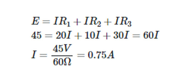
There is an alternative approach to solving Example 1 that can be derived from Kirchhoff’s voltage law.
Series Circuit Example 1A
Find the current through a series circuit with a 45 V source, a 20 V resistor, a 10 V resistor, and a 30 V resistor.
Solution
Characteristics of Series Circuits
The voltage drops in a series circuit can be calculated using Ohm’s law because the current flows equally through each component.

This is achieved by transposing the variables in each set of equivalent terms to

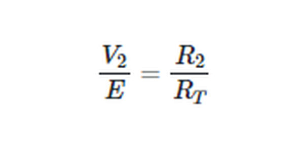
When two resistances are connected in series, the ratio of the voltage drops across them is equal to the resistance ratio.
These ratios will help us skip a few calculations when trying to determine a series circuit’s required value for a given parameter.
Voltage Drop Calculation Example 2
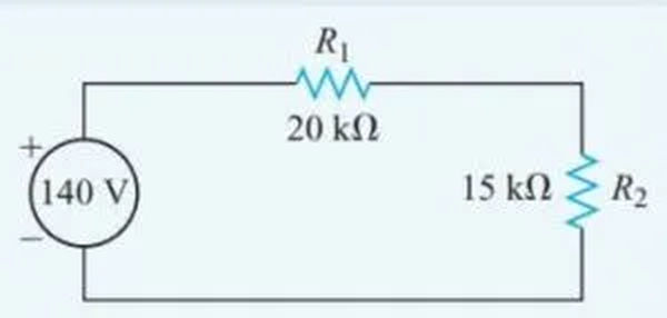
A source of 140 V is connected in series with a 20 kV resistor and a 15 kV resistor. Calculate the current that flows through the 15 kV resistor.
Solution
Figure 4 is an example of a labeled schematic diagram that can be used to better understand the interdependencies in a circuit.
Use ratios to find the voltage drop.
Since,
So,

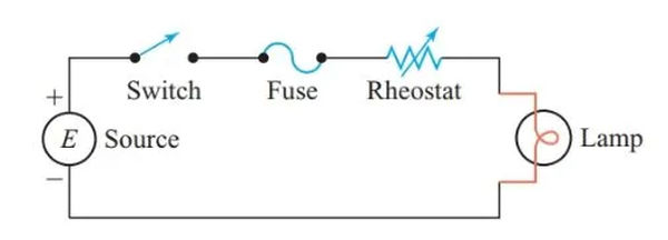
In a series circuit, all components share the same current, so modifying one component has an effect on the others. As can be seen in Figure 5, this requires the load to be connected in series with control components such as switches, fuses, and rheostats.
A series circuit can be identified by its following properties:
- In a series circuit, each component receives the same amount of current.
- All the individual resistances add up to the total resistance.

- In other words, the sum of all the voltage drops is equal to the applied voltage.

- The voltage drop ratios are proportional to the resistances.
- In a series circuit, the current through all components is affected by a change in a single component.
Cells in Series
The typical cell’s nominal voltage ranges from 1.1 V to 1.5 V. The maximum permissible current in a cell varies with its size and type.
Parallel connections between identical cells produce greater voltages than either cell operating alone. Since the current through a series circuit is constant no matter where you are in the circuit, the total current rating will be the same as for each individual cell.
If a series connection is made between cells of varying capacities, the cells with the lower capacity will be depleted first. Figure 6 depicts the typical configuration of battery cells used in portable device batteries.
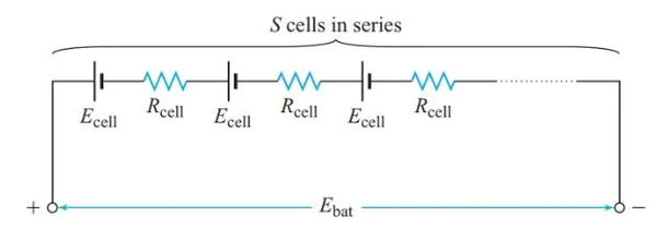
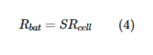
Calculating the total battery EMF requires knowing the number of cells in series (S), the EMF of each cell (Ecell), and the internal resistance of each cell (Rcell).

and the overall internal resistance of the battery is
Current in Series Circuit Example 3
How much current does a battery with 10 cells in series, each with an EMF of 1.5 V and an internal resistance of 0.20 V, produce when connected to an external resistance of 4.0? Try to measure the battery’s terminal voltage.
Solution

The total resistance in the circuit,

Applying Ohm’s law to the whole circuit gives

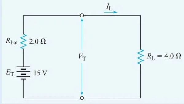
Figure 7 shows the equivalent circuit for the battery.
