The overhead power lines do not have an insulating covering, and the conductors are exposed. Line conductors must be properly insulated, which means they must be supported on the poles or towers in a way that prevents current from flowing to earth through the supports. For this purpose, insulators are used to attach line conductors to a structural element.
The insulator prevents current from leaking out of the lines by isolating the conductors from the supports. Conductors can rely on insulators for support, too.
Overhead Line Insulator Properties
The ideal insulator would have these characteristics:
- Superior mechanical strength to withstand stresses from conductors, winds, etc.
- To prevent electrical current from leaking to ground, insulators feature a very high resistance to electrical current.
- Insulator materials typically have a high relative permittivity, which contributes to their high dielectric strength.
- The permittivity of the insulator will drop if it is not impure and has no pores.
- Extremely low flashover strength in comparison to puncture strength.
Overhead Line Insulator Materials
Insulator units are typically made from one of three common materials.
- Porcelain
- Glass
- Synthetic resin
Porcelain is the standard material for the wires in the ceiling. As a ceramic, porcelain is a versatile and beautiful material. An amalgam of kaolin, feldspar, and quartz is fired at a very high temperature to create it.
Inside the insulator, you’ll find metal components made of malleable cast iron that have been galvanized. It has better mechanical strength than glass, causes fewer leaks, and is less sensitive to temperature variations.
As an alternative to porcelain, glass is also used as an insulator. Glass insulators, on the other hand, are typically only used in extremely high voltage (EHV) AC and DC systems.
The glass is toughened by heat treatment. Though more fragile, the insulator’s transparency makes cracks and other flaws in the material readily apparent to the naked eye.
On the other hand, glass insulators have the drawback that moisture condensation on the insulator surface increases the risk of current leakage.
Most of the time, synthetic insulators are put to use indoors. Silicon, rubber, resin, and other similar compounds are included in their make-up.
Both the strength and the weight of synthetic insulators are greatly improved over those of natural materials. In contrast, the leakage current is higher, and the device’s lifetime is shorter. However, they are more cost-effective than alternative materials and find widespread use in bushings.
Types of Overhead Line Insulators
Below, we’ll go over the different kinds of insulators that are used in transmission and distribution lines high above ground.
1. Pin-Type Insulators

Figure 1 depicts a cross-section of a pin-type insulator. Pin-type insulators, as their name implies, are fastened to the pole’s cross-arm.
An opening is provided at the top of the insulator to secure the wire. Through this notch, the conductor is secured with annealed wire made from the same material.
In order to safely transmit and distribute electricity up to 33 kV, pin-type insulators are utilized. When the operating voltage increases past 33 kilovolts, the cost of the pin-type insulators rises because of their increased size.
1.1. Causes of Insulator Failure
Mechanical and electrical stresses must be withstood by insulators. The latter is usually caused by the line voltage and can lead to the insulator breaking down.
Either flashover or a puncture can cause an insulator to lose its electrical properties.
In the flashover, an arc occurs between the line conductor and the insulator pin (i.e., earth) and the discharge jumps across the air gaps, following the shortest distance.
In Figure 2, we see the insulator’s arcing distance (i.e., a + b + c). As long as the insulator is not destroyed by the extreme heat generated by the arc, it will continue to serve its intended purpose.
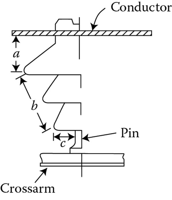
In case of puncture, the discharge occurs from conductor to pin through the body of the insulator. In case of puncture, the insulator is permanently destroyed due to excessive heat.
Because of this, the insulator is made of porcelain and is thick enough that a pin cannot penetrate it. When comparing puncture strength to flashover voltage, the safety factor is the ratio between the two.

It is preferable to have a high value of safety factor so that flashover occurs before the insulator is punctured. As a rough estimate, a safety factor of 10 can be applied to pin insulators.
2. Suspension Type Insulators
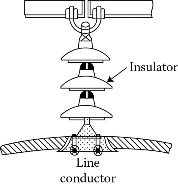
It is common practice to employ the suspension type insulators depicted in Figure 3 when dealing with high voltages (>33 kV). They are strung together from multiple porcelain disks connected in series by metal links.
The tower’s cross-arm is tied to one end of the string, while the other end suspends the conductor. Low-voltage operation is a feature of each individual disk or unit (say 11 kV). The working voltage is the obvious determinant of the disk count. For instance, a string with six disks in series would be provided if the operating voltage was 66 kilovolts.
Advantages
- As the voltage increases past 33 kilovolts, the price of insulators begins to rise.
- Low-voltage operation is a feature of each individual disk or unit (say 11 kV). The working voltage is the obvious determinant of the disk count.
- Damage to a single disk in a string can be remedied by simply exchanging it for a working disk in the same string.
- The setup allows for more maneuverability on the line. Depending on where the mechanical stresses are lowest, the insulator can move in any direction, thanks to the flexibility provided by the cross-arm connection.
- Steel towers typically pair well with suspension insulators. Since the conductors are routed below the tower’s earthed cross-arm, some protection from lightning strikes is afforded.
- In the event of a surge in transmission line usage, it is preferable to meet the additional demand by increasing line voltage rather than adding more conductors. Adding as many disks as needed to the suspension setup provides the extra insulation necessary for the higher voltage
2.1. Types of Suspension Insulators
The types of suspension insulators in use are
- Cap-and-pin type
- Hewlett or interlink type
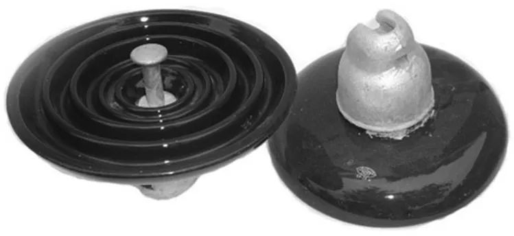
The first variety is the most typical. In the cap-and-pin type of construction, porcelain is attached to either a cast iron cap or a forged steel pin that has been galvanized.
Ball-and-socket and clevis-pin connections are used to join the various sections. Figure 4 depicts a typical construction using a cap and pin.
Porcelain with two curved channels on perpendicular planes is used for the interlink type unit (Figure 5). Through these openings, steel links with a U-shaped cover are able to connect the various modules.
Mechanically, an interlink insulator is superior to a cap-and-pin design. If the porcelain in the gaps between the links breaks, the line is still supported by the metal links. Because of this, there will be no disruption in supply.
As a result of the high electrical stress imposed on the porcelain between the links, the Hewlett type of insulator has a lower puncture strength than other types.
3. Strain Insulators
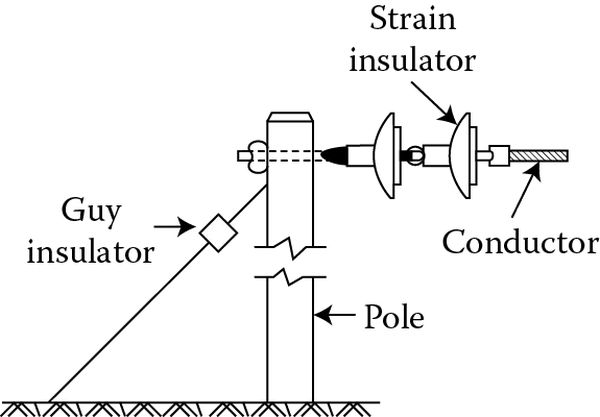
The line’s tension increases when it reaches a terminal point or when it makes a sharp turn. When there is too much pressure on a line, strain insulators are used to release some of that tension.
Shackle insulators are commonly used as strain insulators for low-voltage lines (11 kV and below). But for high-voltage transmission lines, the strain insulator is an assembly of suspension insulators, as shown in Figure 6.
Strain insulator disks find application in the z-axis. Whenever the line tension is extremely high, such as at long river spans, multiple strings are used in parallel.
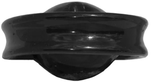
4. Shackle Insulators
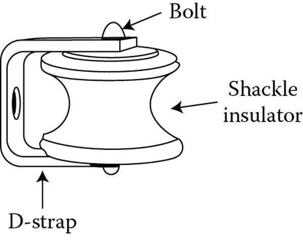
Strain insulators, or shackle insulators, were initially implemented in the early days of the industry. Their primary use now, however, is for low-voltage distribution lines (11 kV and below). You can put these insulators horizontally or vertically, depending on your needs.
They can be bolted either directly to the pole or to the cross-arm. The shackle insulator is pictured in Figure 7 attached to the pole. A flexible binding wire secures the conductive strip in the groove.
5. Stay Insulators
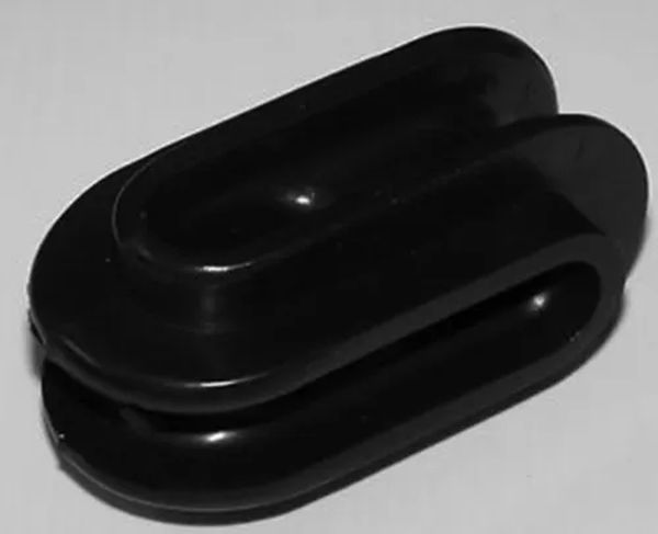
These egg-shaped insulators, which are also known as strain insulators and guy insulators, are installed in guy cables to prevent the ground from becoming electrified and posing a threat to people and animals below.
The guy wires are looped through the insulator’s two holes, which are set at right angles to one another, on either end of the porcelain piece. If the insulator breaks for any reason, the guy wire will remain in place thanks to the compression of the porcelain between the two loops. The stay insulator is depicted in Figure 8.