Motor control panels (MCP) can be found in a wide variety of settings, from oil rigs to cookie factories. By doing so, production can be replicated and automated with minimal involvement from humans. Almost no modern factory operates without some form of automation, typically managed by a motor control panel.
Think of a car factory with a line of vehicles waiting to be assembled. An operator at a motor control panel directs the line’s motors. This motor and production line can pause at each fitting station before continuing on to the next.
It’s possible that the line will have to be halted and restarted several times before it reaches its destination. A motor control panel is capable of performing this action with or without human intervention.
Motor Control Panel Purpose
Control engineers plan the layout of motor control panels, and technicians pre-wire them with a specific logic in mind. This reasoning is geared toward completing or partially automating a task. Any motor will need the standard components found in a control panel.
What makes these parts unique to a particular procedure is the wiring or connection scheme that binds them together. Electromechanical devices such as switches, contacts, relays, motor starters, and overload protectors are all part of the whole. In the following sections of this guide, we’ll examine each of these separately.
There’s more to control panels than just operating motors. They allow us to use a low voltage control circuit to activate or deactivate high power circuits. This not only reduces the user’s energy bill, but it also makes the workplace safer for technicians. To have a system wired with high voltage controls that operators use to start and stop a line or process is extremely risky.
Typically, a motor’s control panel will have a high voltage side (sometimes called “Line Voltage”) for running the motor and a low voltage side (sometimes called “Low Voltage”) for managing the high power circuits.
The standard voltage for use in commercial and industrial settings is 480 volts. A transformer is used to step down the power supply and supply a more manageable voltage, typically 24 volts, to the control circuitry.
Most motor control panels have a “Line Voltage” (high voltage) side for running the motors and a “Low Voltage” side for managing the high power circuits. The standard voltage for industrial use is 480 volts. For the control side, a lower voltage, say 24 volts, is fed from a transformer.
MCP Components-high Voltage Components
By centralizing the origin of the power circuits and control circuits, a motor control panel facilitates the integration of automated control into a production line. The low voltage supplied by motor control panels makes them an important component of safe motor operation.
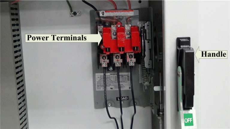
All electrical current going into an MCP must first pass through a safety switch. For clarification, please read on…

Disconnect Device in MCP
The three apexes at the very pinnacle of the power disconnect switch are where the wires are spliced off (1). You can make a physical connection between the two sets of terminals by means of the handle (2). To power the rest of the components, or to access the interior of the panel for maintenance, a technician must manually operate the switch.
The switch is “closed” and power is supplied to the various components when the handle is in the up position, at which point the panel is “live” or “hot.” When the knob is locked in place, power is routed through the distribution block to the low voltage control side, where it is used to power the components and protect the branch circuits from overload.
Fuse sizes are determined by the highest current that can be safely drawn during normal operation.

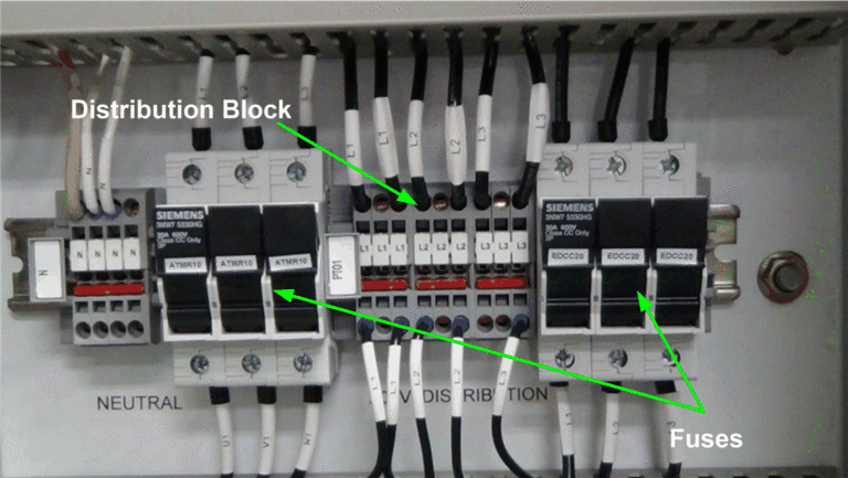
Fuses and Distribution Block in MCP
A fuse is a protective device. As long as the current drawn through the fuse does not exceed its rating, they function as a closed switch. A fuse is a safety mechanism that breaks the circuit if the amount of current drawn from an electrical source is too high, protecting both the device and its user.
Expert replacement by hand is required. It is not possible to use a fuse with a higher amperage to replace one with a lower amperage. If this were to occur, the intended current through the devices could be increased. It poses a risk to both the machinery and the people working on the panels. Fuse protection requires that fuses be replaced with fuses of the same or lower current rating.
Next, the distribution terminals connect the high voltage power source to the variable frequency drive and the motor starter. Due to the high power demands of the loads connected to these devices, they operate at full line voltage.

Variable Frequency Drive (VFD)
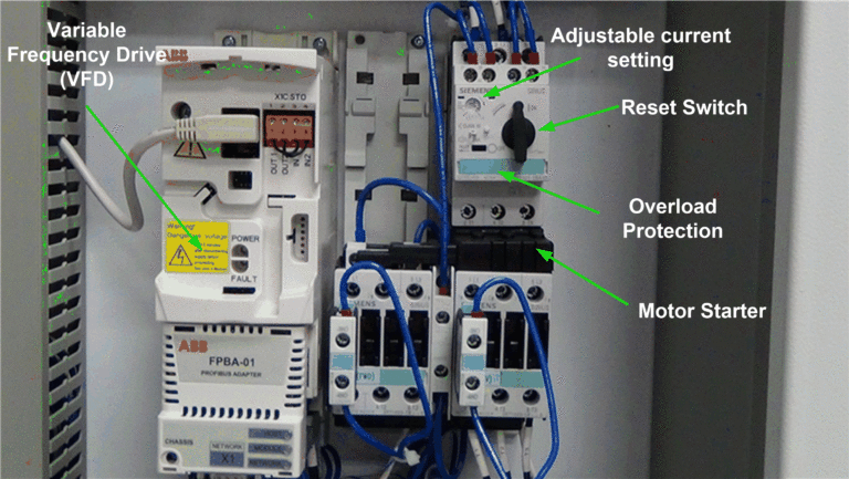
One way to regulate motor speed is with a variable frequency drive (VFD). It’s one of a kind because it can be used to control both the on/off and speed of a motor. This is required for some procedures but not others, making it a piece of machinery that can be used or not.
Later, we’ll talk at length about VFDs. Only the fact that it is a high-voltage part meant to regulate motor speed is relevant here.
Motor Starter
Motor starters have two main parts: a contactor for high-voltage flow and an overcurrent protection device in case of an error. A motor’s full line voltage can be supplied by a starter. Switching the starter on and off from the low voltage side requires a lower voltage.
The coil voltage is then drastically reduced to a much lower and safer value, such as 110 or 24 volts, for use in a practical setting. The starter’s contacts connect to the line voltage and send it to the motor when the coil voltage is turned on.

One or both of the motor starter’s contactors may be electrically or mechanically locked to the one next to it. Because of the interlock, neither contactor can be powered on at the same time. This allows us to reverse the rotation of the motor shaft when necessary. A forward-reverse motor starter is what you need.
Overcurrent protection is always an integral part of a motor starter’s design. In the event that the motor draws more current than expected, this will prevent damage to the control panel and its components.
Overload protection like the one shown above can be customized to fit a wide variety of motors thanks to its adjustable current setting and reset button. The switch will immediately cut power to the circuit if something goes wrong. After the problem has been fixed, the motor starter can be reset by hand.
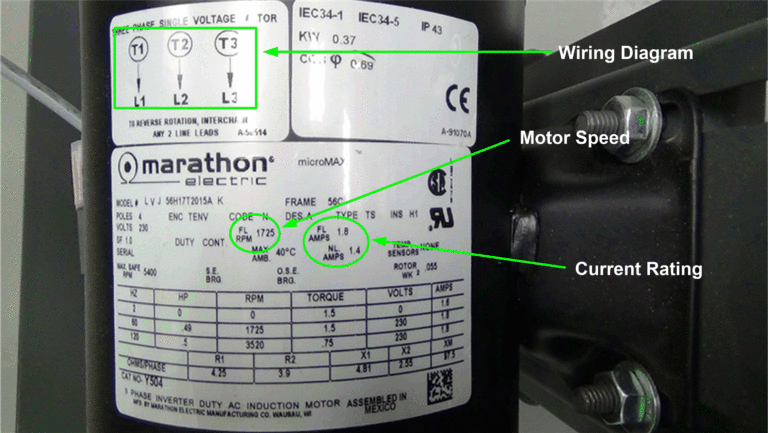
A fixed-speed motor requires a motor starter. Physically connecting the motor to the starter’s terminals is required. A technician should be able to find the motor’s wiring diagram, current draw, voltage, and speed on the motor data plate (below).
The voltage, frequency, and amperage of a motor starter must match the requirements of the load or motor it is starting.