Four primary varieties of direct current (DC) motors exist: the DC series motor, the DC shunt motor, the DC compound motor, and the DC permanent-magnet motor. Although visually similar, the internal construction and output performance of these DC motors are quite distinct.
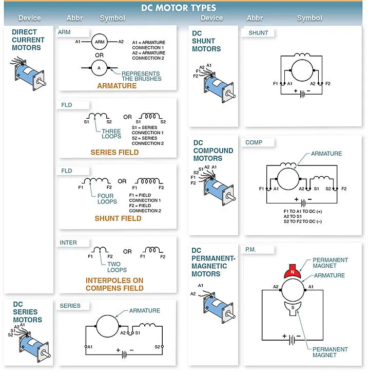
The shunt field leads (F1 and F2), series field leads (S1 and S2), and armature leads (A1 and A2) of a DC motor are all clearly labeled. Leads A1, F1, and S1 are typically connected to the positive power side of a DC motor, while leads A2, F2, and S2 are typically connected to the negative power side.
DC Series Motor
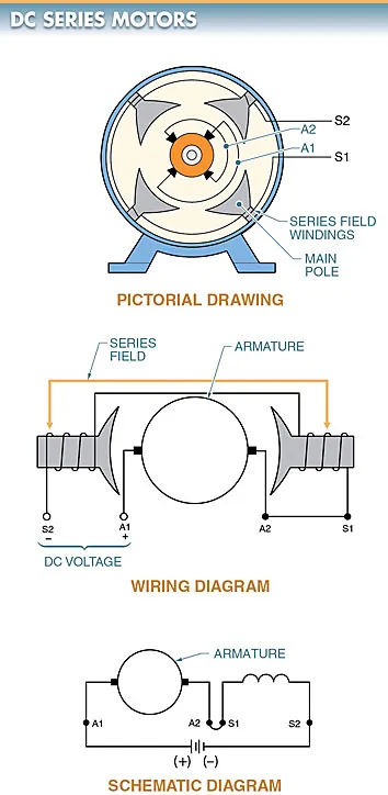
A DC series motor is a DC motor that has the series field connected in series with the armature. The field must carry the load current passing through the armature. The field has relatively few turns of heavy-gauge wire.
S1 and S2 indicate which wires go where from the series coil. The armature’s protruding wires are labeled A1 and A2. Refer to Figure 2.
DC Series Motor Characteristics
The starting torque of a DC series motor is very high. View Figure 3. When it comes to motors, the field coil (series field) is always connected in series with the armature.
A DC series motor’s high starting torque makes it well-suited for applications where the starting load is significant, despite the motor’s poor speed control. Cranes, hoists, electric buses, streetcars, railroads, and other heavy-traction applications are just some of the places you’ll find this technology in action.
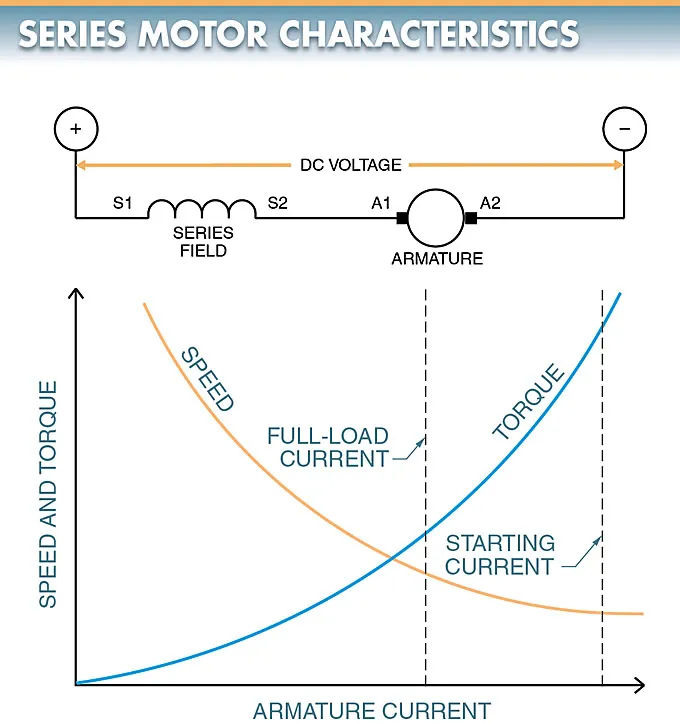
A motor’s torque is proportional to the intensity of its magnetic field. Magnitude of magnetic field is proportional to current in series field.
Current consumption by a motor is proportional to the load applied to it. In other words, the greater the load, the more current will be flowing.
Since the armature and series field are connected in series, an increase in load results in an increase in current through both components. The high torque output of a DC series motor is the result of the increased current flow that this design allows.
DC Series Motor torque speed Characteristics
In DC series motors, speed changes rapidly when torque changes.
When the torque is high, the speed is low, and vice versa. This is due to the massive flux increase caused by the increased current (caused by the load) flowing through the series field. When the flux is increased, a large counter electromotive force is generated, which significantly slows down the motor.
As soon as the load is removed, the motor’s speed increases dramatically. The motor’s speed would increase unpredictably if it weren’t for the load. Occasionally the velocity can get high enough to cause motor failure. This is why it’s never a good idea to use a belt, chain, or other transmission method when connecting a DC series motor to its load.
DC Series Motor Speed Control
With a DC series motor, changing the voltage applied to the motor changes its speed. A shunt motor’s speed regulation is superior to that of a series motor, but not all uses necessitate such precision.
In some cases, like the starter motor in a car, the benefit of a high torque output outweighs the advantage of good speed control.
DC Shunt Motor
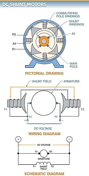
A DC shunt motor is a DC motor that has the field connected in shunt (parallel) with the armature.
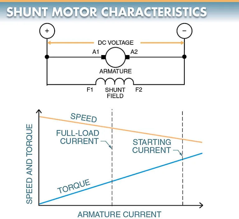
In a DC shunt motor, the two leads coming off the shunt field are labeled F1 and F2. A1 and A2 indicate which windings go where on the armature. Please refer to Figure 4.
This is because the DC shunt motor’s field has many turns of wire and its current is not dependent on the armature.
The shunt field can use the same power source as the armature, or it can use a separate power source.
If the shunt field and armature share the same power source, we say that it is self-excited. A shunt field that is excited by a source other than the armature is said to be “separately excited.”
DC Shunt Motor Applications
Use DC shunt motors when starting conditions are relatively mild and you need a constant or variable speed.
Fans, blowers, centrifugal pumps, conveyors, elevators, woodworking machinery, and metalworking machinery are all common examples of devices that make use of this principle.
DC Shunt Motor Characteristics
Bringing down the voltage to the armature of a DC shunt motor slows it down. The motor’s rotational velocity increases as the magnetic field’s strength decreases.
Since the counter electromotive force developed in the armature of a DC shunt motor is proportional to the square of the shunt field strength, decreasing the shunt field strength causes the motor to speed up. Torque and speed are increased when the counter electromotive force is decreased because of the higher armature current.
The speed of a DC shunt motor can be adjusted by changing either the armature voltage or the shunt field current. View Figure 5.
DC Shunt Motor Speed Control
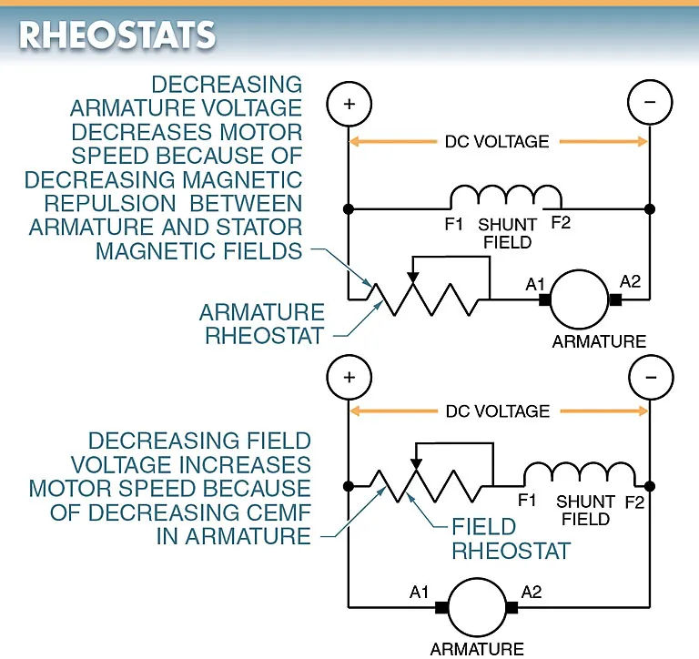
The speed of a DC shunt motor can be changed with a field rheostat or an armature rheostat. Refer to Fig. 6.
The rheostat is used to increase or decrease the strength of the field or armature. Once the strength of the field is set, it remains constant regardless of changes in armature current.
When the armature is subjected to a greater load, the motor’s armature current and torque rise accordingly. As the armature slows, the CEMF drops, allowing the armature current to be raised and the motor to resume its original speed. It seems that regardless of what you set the speed control to, the motor operates at a relatively constant rate.
DC Shunt Motor Torque-Speed Characteristics
Any speed at which a DC shunt motor is operating produces a relatively high torque. For a given armature current, the motor’s torque is proportional to that current. More current through the armature increases motor torque with only a marginal reduction in speed.
DC Compound Motor
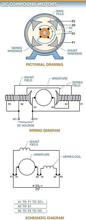
A DC compound motor is a DC motor with the field connected in both series and shunt with the armature.
Series field (S1 and S2) and shunt field (F) combine to form the field coil (F1 and F2). 7th Figure
DC Compound Motor Characteristics
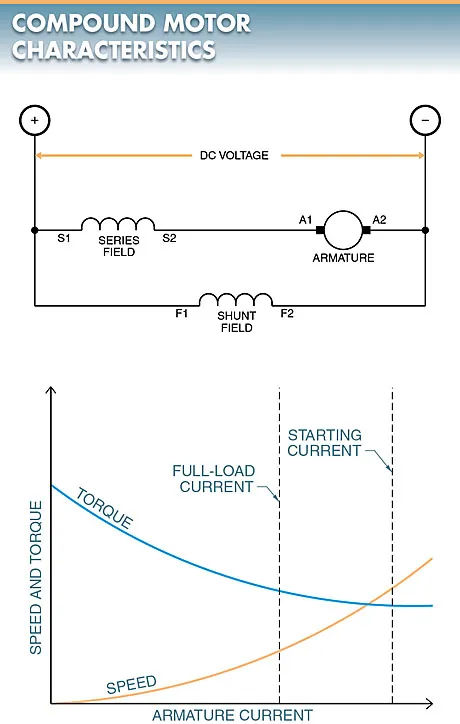
The armature and the series field are linked together in a series connection. The armature and series field are linked together in parallel.
The motor benefits from both the high torque of a DC series motor and the low resistance of a DC shunt motor thanks to this configuration (constant speed). Refer to Fig. 8.
DC Compound Motor Applications
When both high starting torque and constant speed are needed, DC compound motors are the way to go. Punch presses, shears, bending machines, and hoists are just some of the commonplace uses.
DC Compound Motor Speed Control
Speed control is obtained in a DC compound motor by changing the shunt field current strength or changing the voltage applied to the armature. In order to achieve this, either a variable voltage supply or a controller that employs resistors to lower the applied voltage is used.
DC Permanent-Magnet Motor
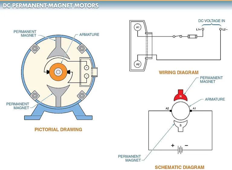
A DC permanent-magnet motor is a motor that uses magnets, not a winding, for the field poles.
For DC permanent-magnet motors, the magnets are molded and then mounted in a steel housing. As for the field coils, they are the permanent magnets. However, only the armature receives DC power. Examine the diagram in Figure 9.
DC Permanent-Magnet Motor Applications
Automotive applications for DC permanent-magnet motors include the operation of electrically powered seating, windows, and wipers.
DC Permanent-Magnet Motor Characteristics
When the power is cut off, DC permanent-magnet motors can partially self-brake and produce a lot of torque. DC permanent-magnet motors can quickly become too hot to operate reliably in a continuous-duty setting, so they are not always suitable for such a task. Heat kills the permanent magnets.