Capacitance is a material object’s or device’s ability to retain electric charge. It is measured by the change in charge in response to a variation in electric potential, expressed as a ratio of those values.
Capacitance is defined as the resistance to a voltage change. A capacitor is an electromechanical storage device.
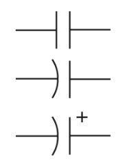
A capacitor either takes in the charge or releases it to keep the voltage stable. The capacitor symbols used in schematic representations are depicted in Figure 1.

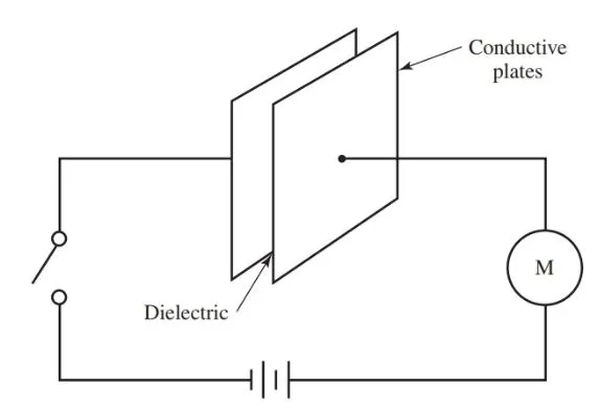
The capacitor has insulation between its two conductive plates. The term “dielectric” is used to describe this type of insulating material in Figure 2.
A dc voltage source is shown in the diagram, which is connected to the plates. When the plates are not touching, the circuit gives the impression of being open. But the circuit meter will still show current flow for a while after the switch is closed.

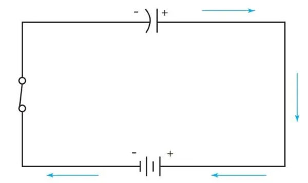
As shown in Figure 3, when the switch is closed, electrons from the negative terminal of the source flow to one plate of the capacitor. For the same reason that like charges are repelled from one another, electrons from the second plate are attracted to the positive terminal of the source. The capacitor’s charge is now equal to the source’s, so it acts as a voltage regulator by blocking the supply.
The capacitor will retain its charge even if it is disconnected from the circuit. Capacitors are used because their electric fields can store energy for later use. After the capacitor is charged to its maximum capacity, the circuit will no longer conduct electricity.

It is critical to keep in mind that the capacitor in the circuit shown in Figure 3 did not receive any electron flow. Why? Because a capacitor can’t conduct dc, so this can’t happen. However, a negative charge was developed on one plate and a positive charge on the other. The space between them is permeated by a powerful electric field.
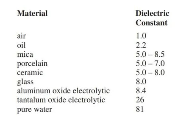
Insulating or dielectric materials vary in their ability to support the electric field. This ability is known as the dielectric constant of the material.
Figure 4 presents the constants for a number of common materials. These measurements are in agreement with those obtained by comparing dry air’s dielectric constant. A value of 1 has been chosen to represent dry air.

Capacitor Working Voltage
Capacitors have a limited voltage range because of the dielectrics they use. For voltages above this threshold, dielectric breakdown and arcing become inevitable. The term “working voltage” refers to this maximum potential (WV).
The dielectric and any other components in the circuit could be damaged if the voltage applied to it was greater than its working range.
Materials with higher voltage ratings and dielectrics with greater thickness are required. It is important to verify the dc working voltage and capacitance value of a replacement capacitor.
A capacitor’s working voltage in an ac circuit must be higher than the peak ac voltage to prevent damage to the component. An effective ac voltage of 120 volts, for instance, has a peak voltage of 120 V 1.414 = 169.7 V. Capacitors must have a minimum voltage rating of 169.7 volts.
Capacitance Calculation Formula
For each volt of applied voltage, the capacitance of a capacitor is equal to the number of electrons it can store. It is the farad that is used to quantify capacitance (F). A charge of one coulomb produces a one-volt increase in potential, and this is what a farad measures. Here is the formula:
C = Q/E
Capacitance is denoted by C, charge by Q, and voltage by E.
Microfarads are used for capacitors with a capacity of 1/1,000,000 F, and Picofarads are used for capacitors with a capacity of 1/1,000,000 F. For microfarad, use either mfd or μF. pF stands for “picofarad,” which is the unit of measure commonly used. Capacitance values in the nanofarad range are unusual.
Figure 5 displays a conversion chart in these units.

Capacitance is determined by:
- The substance that plays the role of dielectric. (The capacitance increases as the dielectric constant increases.)
- A measurement of the plate’s surface. (The capacitance increases as the surface area of the plate does.)
- Just how far apart the plates are. (The capacitance increases as the separation between two points decreases.)
- The mathematical formula connects these variables:

In this equation, C is the capacitance in Picofarads, K is the dielectric constant, A is the area of one side of a plate in square inches, d is the distance in inches between the plates, and n is the number of plates.
It is clear from this formula that:
When the area of the plates or the dielectric constant is increased, the capacity also grows.
Distancing the plates has a negative effect on capacity.
A lesson in Safety
It may take some time for the charge to completely drain from the large capacitors found in televisions and other electronic equipment. To discharge these capacitors, use an insulated screwdriver to short their terminals to the chassis of the equipment.
Inadequately discharging capacitors can result in severe shocks to technicians and the destruction of test equipment.