A vacuum tube is a device that controls the passage of electric current in a high vacuum between electrodes with an electric potential difference. It also called electron tube, valve (British usage), or tube (North American usage).
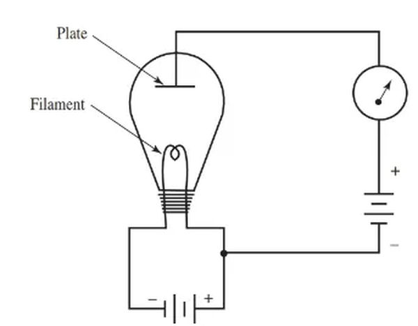
Thomas Edison’s work with the incandescent lamp led directly to the development of the vacuum tube. A metal plate was placed inside the vacuum bulb with the filament in this experiment. Between the light bulb and the plate were a battery and a series meter.
When Edison connected the battery’s positive terminal to the plate, he found that current flowed through the bulb. Nonetheless, current would not flow if the negative battery terminal was connected to the plate. For an example, see Fig. 1.
It was a mystery how current traveled through the light before the discovery of the electron theory.
The theory of electrons is now well understood. When heated, some metals and metal oxides release free electrons. The electrons receive enough energy from the heat to emancipate themselves from the orbital forces. Once released, the electrons are no longer bound. The term “thermionic emission” is used to describe this phenomenon.
In Edison’s experiment, the light bulb’s filament released a cloud of free electrons. After placing a positive plate inside the light bulb, the free electrons were drawn to the plate. (Electrons of dissimilar charge attract one another.) The presence of a current is indicated by the movement of electrons.
Electric current was detected between the filament and plate, as measured by the meter connected to the plate circuit. This vacuum tube operates on the same principles that Thomas Edison developed in his lab.
Thermionic Emitters
In the years since Edison’s carbon filament was invented, better emitting materials have been developed. When heated to the point of emission, many materials will melt.
Tungsten was widely regarded as superior to other metals for a long time. It was tough and long-lasting, but it needed a lot of heat for proper emission. Large, high-power vacuum tubes still frequently use tungsten.
The thoriated-tungsten emitter was created to reduce operational temperatures and energy consumption. A thin layer of thorium was deposited onto the tungsten emitter to create this.
The element thorium is extremely dense and heavy relative to other metals. Th is its chemical symbol, and its atomic weight is 232.04. This emitter type is much more efficient than pure tungsten at producing the desired emission at lower temperatures.
The oxide-coated variety of emitter is the most productive. The light source is a metal like nickel. A very thin layer of barium or strontium oxide forms on the emitter. This type of emitter was commonly used in vacuum tubes for radios, televisions, and other electronics due to its low power consumption and high emission.
Cathodes
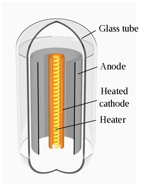
The cathode is the part of a vacuum tube that emits light. Direct and indirect heat sources are both possible. There are benefits to using either approach. Figure 2 displays schematic representations of both tube varieties.
Directly heated cathodes are ideal for use in battery-powered equipment. Less energy is wasted as heat, and the filament can be made more efficient to further cut down on power use.

Indirectly heating the cathode is preferable when an AC source is available. Very little energy is wasted, and the cathode and heater voltage source are no longer intermingled. The humming in the circuit is now completely gone.
Diodes
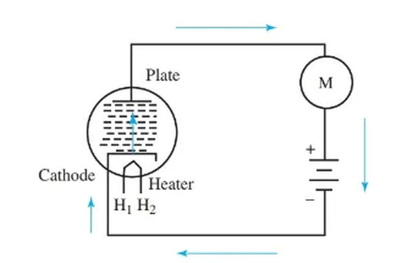
There are two electrodes in a diode. In a vacuum tube diode, the cathode and plate are the two electrodes. Once again, the cathode can be heated either directly or indirectly. The tube’s contents are contained within a circular metal plate. The plate is used to collect the electrons released by the cathode. View Figure 3. H1 and H2 are the terminals for the heating system. These plugs can be connected to an alternating current supply.
In general, the voltage supplied to the heaters of a tube should be close to the number indicated by the first digit of the tube’s name. As an illustration, the voltage requirements of a 6H6 tube are 6.3 volts, those of a 12AX7 tube are 12.6 volts, and those of a 25Z6 tube are 25 volts.
The cathode in the tube depicted in Figure 3 is indirectly heated by the heaters when the device is turned on. The result is an effect known as thermionic emission of electrons. By connecting the cathode of the battery to the diode’s plate, electrons can flow from the cathode to the plate. No electrons will flow if the connections are switched. It’s a one-way valve for electrons, this vacuum tube. One-way electron flow is allowed.
The cathode’s maximum rate of electron emission occurs at a specific temperature. There is a charge around the cathode because of these electrons. After electrons have been emitted from the anode, the cathode will have a slight positive charge. An amount of these electrons are drawn to the cathode.
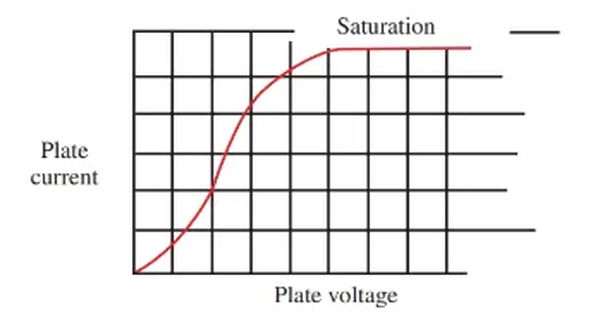
Many electrons are drawn to the plate after it has been made positive. These currents represent the movement of electrons. To increase the plate’s positivity, a higher voltage can be applied. There is a rise in current due to the increased attraction of electrons.
More plate voltage leads to more current, as shown in Figure 4. As the applied voltage rises, eventually all the released electrons will be drawn to the plate. More voltage will not produce more current. That’s when the electron tube reaches its saturation point.
Triodes
A triode consists of a cathode, plate, and grid, making it a three-element tube. Dr. Lee DeForest invented the triode. DeForest used a very fine wire mesh in his experiments to separate the cathode from the tube’s plate. This allowed him to regulate the flow of electrons within the tube. This framework, made of wire, serves as the grid.
The triode’s grid typically takes the form of a cylinder and encloses the cathode. In order for electrons to reach the plate, they must first travel through the space between the grid wires. The grid, also known as the control grid, regulates the flow of electrons.
Altering the voltage between the plates regulates the current of electrons. Even in the triode, electron flow can be affected by the grid. Many electrons, for instance, would be repelled back to the cathode if the grid were negatively charged. As a result, fewer electrons make it to the plate.
Eventually, if the grid is made negatively charged enough, no electrons will reach the plate. The end of the tube is located here. The application of a negative voltage to the control grid effectively cuts off electron flow. The term “bias voltage” describes the voltage that is used to power the regulation grid. The bias at the cutoff point is known as the cutoff bias.
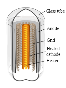
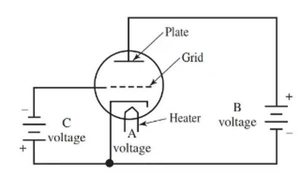
Figure 5 depicts a triode with applied voltage to both its plate and its grid. Observe that the negative terminal of the grid bias battery is attached to the grid. Electronics use a system of naming these voltages, such as A, B, and C.
The tube’s heaters require the higher A voltage. The plate of the tube requires a voltage of type B. The grid of the tube requires the higher C voltage.
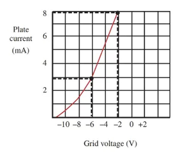
In Figure 6, we see the impact of altering the grid bias on the current flowing through an electron tube. The plate voltage is held at a constant value. This graph’s curve was generated by recording the magnitude of the current at various grid voltages. An eight milliampere current flows when the grid bias is minus two volts. Current decreases to 3 mA at 6 V.
Tetrodes
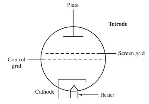
Due to the shunting effect of electrode capacitance at high frequencies, the triode is limited as an amplifier without neutralization circuits, as shown in Figure 7. To address this shortcoming, an additional grid is added to the triode. The screen grid is a fixed arrangement of squares. Between the control grid and the plate, it provides a buffer zone. The resulting four-element tube, consisting of a cathode, control grid, screen grid, and plate, is known as a tetrode (Figure 8).
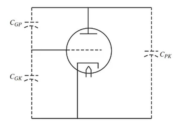
Capacitor externally bypasses the screen grid to ground. The grid effectively blocks the capacitance between the control grid and the plate (CGP).
The grid of the screen is subjected to a direct current voltage that is slightly lower than the voltage of the plates. The screen’s grid accelerates electrons as they travel from cathode to plate. Since there are now electrons stuck to the grid, the screen is generating a current. While some are blocked, the vast majority of electrons make it to the plate.
The tetrode’s control grid is located so close to the cathode that it allows for very powerful amplification. The screen grid’s isolating effect means that changing the plate voltage has minimal effect on the plate current.
Pentodes
A pentode is comprised of five elements, as opposed to four in a tetrode. The electrons in the tetrode accelerate so they can make a hard impact on the plate. When this happens, the plate’s flimsily held electrons are dislodged into the vacuum of space. All of them cluster together to create a space charge around the plate. There’s a name for this phenomenon: secondary emission.
As a result, some of these electrons are attracted to the display. That’s because they interfere with the tube’s ability to carry a useful plate current. The effect is stronger when the plate voltage is lower than the screen voltage.
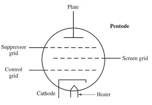
By inserting a third grid between the screen grid and the plate, the drawbacks of secondary emission can be mitigated. Suppressor grid describes this pattern of squares. There are now five components inside the tube (cathode, control grid, screen grid, suppressor grid, and plate). Figure 9 depicts a pentode, which is a type of tube.
Internally, at cathode potential, the suppressor grid is linked to the cathode. Those secondary-emitted, free electrons are repelled by the grid and forced back to the plate.
A high plate resistance and a high amplification factor characterize these tubes. Minimal capacitance exists between the electrodes. Once upon a time, pentodes were widely used in rf amplifiers and audio power amplifiers.