A power distribution system is comprised of the wires, poles, transformers, and other equipment required to transmit electric power to customers at the proper voltages.
After receiving bulk electrical energy from a transmission or subtransmission substation, the primary aim of an electricity distribution system is to meet the energy demands of customers. Distribution substations are classified into two types: primary substations and customer substations.
One Line Diagram in Power Distribution System
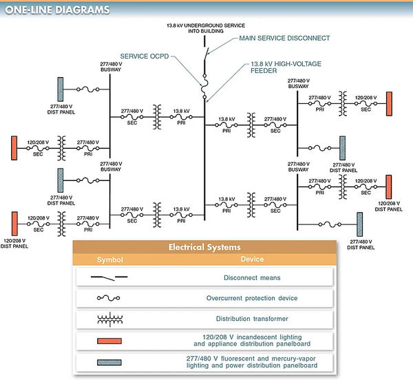
A one-line diagram is a type of electrical drawing that uses only one line and graphical symbols to depict electrical components, such as switches, fuses, circuit breakers, transformers, and panelboards, in a system of electrical distribution.
Since the purpose of a one-line diagram is to clearly depict the flow of electricity throughout the building’s distribution system and the location of each component or device connected to the system, the simplest symbols are used.
When planning the electrical infrastructure for a large commercial or industrial building, one-line diagrams are often used to depict the flow of wires.
Power outages, low voltage, blown fuses, tripped circuit breakers, and poor power quality are just some of the issues that can be diagnosed with the aid of one-line diagrams used in troubleshooting distribution systems.
They are also used to identify potential power outages, plan for future growth, and locate secondary power sources in the event of an emergency.
A one-line diagram can show the entire distribution system or specific parts of a system, which is useful when troubleshooting an electric power system. For an example, see Fig. 1.

One-line diagrams can show complex systems with many moving parts, such as the 13.8 kV feed into a building and the transformers used for voltage distribution.
The distribution of large amounts of electricity over relatively small conductor sizes requires the use of high voltages. Then, the low voltage is delivered to distribution panels after the high voltage is reduced by a step down transformer. Power is distributed to various loads, such as appliances, motors, lights, and computers, via distribution panels.
Feeders and Busways
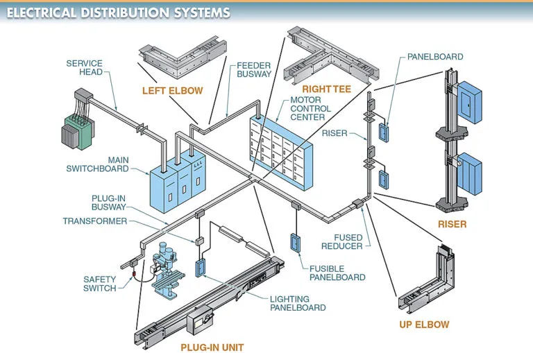
A building’s electrical distribution system is responsible for delivering electricity from the building’s power source to the loads. Large buildings often have complex electrical needs that must be met across a wide range of locations. Observe the second figure.
Changing the distribution system is commonplace in industries where production machinery is frequently relocated.
A busway is a metal-enclosed distribution system of busbars available in prefabricated sections. Prefabricated fittings, tees, elbows, and crosses simplify the connection and reconnection of the distribution system.
After the various pieces have been assembled using bolts, electricity can be found in many different spots.
Conductors in a busway are covered up. This is due to the fact that the electrical current in a plant’s distribution system is very high. Busway conductors are shielded from the high voltage by insulating blocks and an enclosure.
Fast machine hookup and disconnection is facilitated by a busway distribution system. With busways, factories can be retooled or reengineered without having to overhaul their distribution network.

The typical busway is 10 feet long. If a shorter duration is required, it will be used. Electricity can be routed up and down and around corners, and then tapped off from the distribution system, thanks to prefabricated elbows, tees, and crosses. As work is done on installations, the distribution system benefits from the simplicity and ease of its connections.
Busways Types
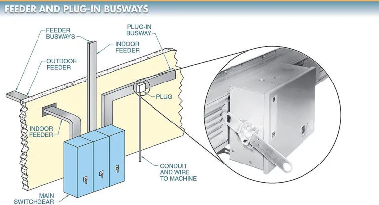
Feeder busways and plug-in busways are the two primary varieties. View Figure 3.
The power is transmitted from the generator to the load via the feeder busways. Similarly to how feeder busways distribute power, plug-in busways do the same thing, but they also make it easy to install new devices that require power wherever they may be located along the bus.
The busway system is powered by a plug-in power panel. Fuse switches, circuit breakers, and specialty plugs like duplex receptacles with circuit breakers and twist-lock receptacles are the three main types of plug-in power panels used with busways.
In order to power a machine or load, electrical conduit and wire must be routed from the plug-in circuit breaker and fusing panels. Power cords are only allowed to be used with transportable devices.

Many times, the loads that are wired into the electrical power grid are not known or are easily transportable. Because of this, it is essential that power distribution systems be designed to allow for the easy addition of loads in the future. An electrician installs outlets all over a structure or factory to provide power for various appliances. These outlets make it simple to connect a variety of loads.
It is important to be able to tell the difference between the voltage and current ratings of each termination because the distribution system’s wiring and protective devices dictate the maximum allowable load size. This is particularly true in industrial settings, which often necessitate the use of multiple currents, voltages, and phase configurations.
Grounding
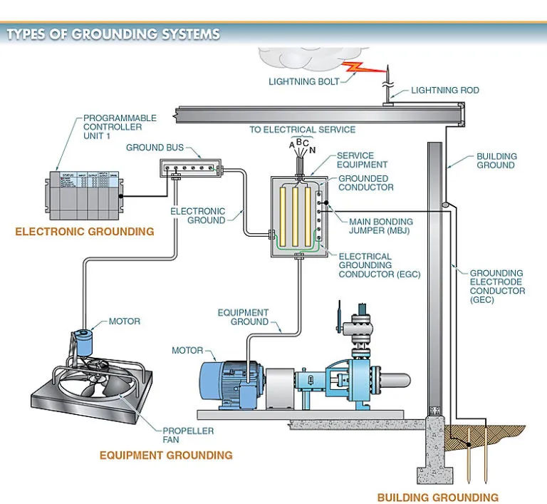
Any electrical power distribution system would be useless without proper grounding of all equipment. Metal components that are not carrying current, such as conduit, raceways, transformer cases, and switchgear enclosures, must be connected to ground.
The goal of grounding is to ensure that all metal components have a low voltage relative to the ground and to create a reliable path for ground-fault current to flow in the event of a fault. For evidence, see Figure 4.

To achieve grounding, an approved grounding conductor and fitting are used to connect the non-current-carrying metal to a ground.
A ground bus is a network that ties solidly to grounding electrodes. A grounding electrode is a conducting object through which a direct connection to earth is established.
Multiple points of contact between the ground bus and grounding electrodes are required. The current through the grounding system and how long the current flows determine the size of the ground bus.
Lightning arresters may be required in addition to properly grounding all conductive metals. Transformers and other electrical equipment can be shielded from lightning-induced voltage surges by installing a lightning arrester.
By creating a path for the surge to travel to the ground, lightning arresters protect electrical systems from potential harm.
Never assume a metal box is properly grounded just because it’s made of metal. Enclosures that aren’t grounded pose a shock hazard if the metal handle of a circuit breaker is touched.