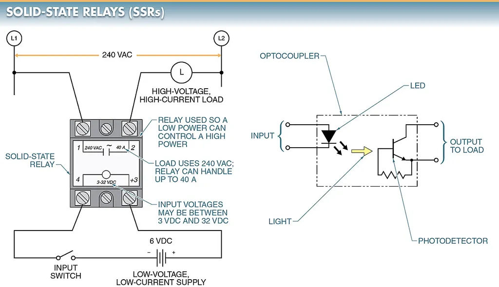
A relay is a switch that opens and closes another circuit to regulate the operation of the first. Applying a low voltage to a relay causes it to switch over to a higher voltage. The electronic switching in a solid-state relay (SSR) eliminates the need for mechanical contacts.
Instead of using mechanical contacts, an SSR uses the output of a silicon-controlled rectifier (SCR), triac, or transistor to switch the controlled current. Within the relay, an internal light-emitting diode (LED) is coupled optically to the output. When the LED is powered, typically with low-voltage DC, the relay activates.
Solid-state electronics are now the norm in the industrial control market. Many devices that previously relied on mechanical and electrical principles are being phased out in favor of solid-state alternatives due to their lower price, greater reliability, and vastly expanded functionality.
Solid-state relays are chosen for specific applications based on their electrical, mechanical, and financial specifications.
Solid State Relay Circuit
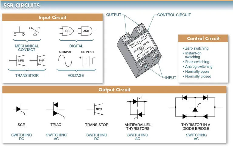
A solid state relay circuit has three parts: the input circuit, the control circuit, and the output (load-switching) circuit. There are a wide variety of solid-state switching applications that can be implemented using the aforementioned circuits.
1. Input Circuit
The section of a solid-state relay (SSR) to which the controller is attached is called the input circuit. An EMR’s coil is functionally equivalent to the input circuit.
Sending a current through the input of the relay at a level greater than its pickup voltage will trigger the input circuit. When an input voltage is applied that is lower than the relay’s minimum dropout voltage, the input circuit will be disabled.
A standard input voltage for some SSRs is 12 VDC. The input voltage range of most SSRs is somewhere around 3 VDC to 32 VDC. Because of the wide voltage range, a single SSR can power the vast majority of modern electronic systems.
A solid-state relay’s input voltage can be switched via mechanical contacts, transistors, digital gates, etc. The majority of SSRs can be switched directly by low-power devices like integrated circuits, without the need for additional buffers or current-limiting components. The input voltage of an SSR can also be switched using variable-input devices like thermistors.
2. Control Circuits
That portion of a solid-state relay called the “control circuit” is responsible for switching on and off the relay’s output device.
The input and output circuits communicate with one another through the control circuit. The interface in a solid-state relay (SSR) is implemented by electronic circuitry within the SSR itself. In an EMR, a magnetic coil closes a set of mechanical contacts to create the interface.
To switch or not to switch depends on whether the relay is a zero switching, instant-on, peak switching, or analog switching relay when the input voltage is received by the control circuit.
In response to a certain voltage, each relay activates the load-switching circuit. A zero-switching relay, for instance, will not switch on the load until the voltage across it has dropped to zero or below. There are a number of advantages to the zero-switching function, including the elimination of high inrush currents on the load.
3. Output (Load-Switching) Circuits
This is because the load switched by an SSR is the SSR’s output (load-switching) circuit. An electromechanical relay’s mechanical contacts are functionally equivalent to the output circuit. Nevertheless, SSRs typically only have a single output contact, as opposed to the multiple contacts on EMRs.
Typically, a thyristor is used for the switching of the output in solid-state relays. When the gate is turned on, the thyristor rapidly transitions from the OFF (contacts open) state to the ON (contacts closed) state. The ability to rapidly switch loads is made possible by this switching mechanism.
The type of load being managed will determine the output switching device used. Different outputs are required when switching DC circuits than are required when switching AC circuits.
Some typical examples of output switching devices found in SSRs are as follows:
- SCRs are used to switch high-current DC loads.
- Low-current alternating current (AC) loads are switched using triacs.
- Low-current direct-current (DC) loads can be switched using transistors.
- It is common practice to use anti-parallel Thyristors for switching high-current AC loads. To a greater extent than a triac, they can release excess heat.
- Low-current AC loads can be switched with thyristors in diode bridges.
Solid State Relay Circuit Capabilities
Most of the circuits that an EMR controls can also be operated with a solid-state relay. Due to the functional differences between an SSR and an EMR, the control circuits for the two types of rectifiers are distinct. The relay’s connection to the circuit is the key difference. The circuit functions of an SSR and an EMR are identical, but the SSR uses a slightly different control circuit to accomplish its tasks.
Two-Wire Control
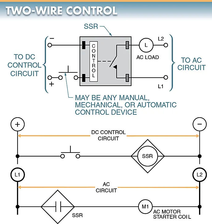
A solid-state relay can be used to switch an electrical load with a momentary switch. Examine the illustration in Figure 3. A push button activates the SSR, which in turn activates the load in this circuit.
To keep the load on, you have to keep your finger on the button. When the button is released, the load stops. For all intents and purposes, this circuit is a direct analog of the conventional two-wire control circuit found in electromagnetic relays, magnetic motor starters, and contactors. So, the pushbutton could be replaced with any other ON/OFF control device, whether it’s manual, mechanical, or automatic.
By switching out the pushbutton for a float switch, the same circuit can be used to regulate the volume of a liquid.
Three-Wire Memory Control
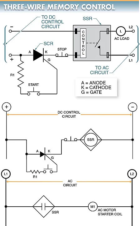
If you want to latch an ON state on a load, you can use an SCR in conjunction with a solid-state relay. Please refer to Figure 4. In every way, this circuit mimics the behavior of a regular three-wire memory control circuit.
Once the start button is depressed, additional storage is added using an SCR. An SCR can switch current from being off to on.
When no gate current is applied, the SCR blocks the DC control current. To activate the SCR, there must be a flow of a certain minimum current. Once the start button is depressed, this will occur.
When the start button is depressed, the SCR’s gate receives voltage, and the SCR is latched in the ON condition, allowing the DC control voltage to pass through even after the button is released.
The value of the gate current-limiting resistor, R1, is a function of both the supply voltage and the gate current.
When programming a motor drive, the control circuit needs to be set up for two-wire or three-wire operation.
When a switch has “two-wire,” it means it can serve dual purposes. A “three-wire” switch can only be used for one purpose. There is no way to control the load with just one three-wire switch.
Equivalent NC Contacts
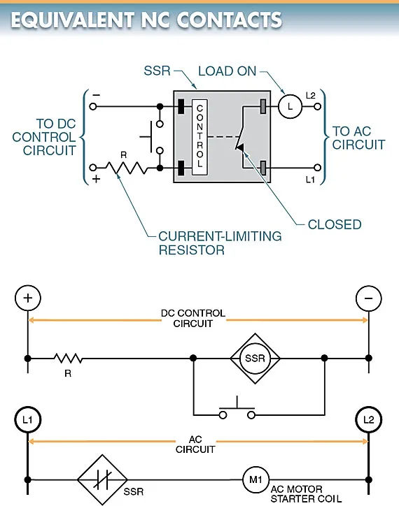
A normally closed (NC) contact condition can be emulated with a solid-state relay. Because most SSRs feature a normally open (NO) contact, an NC contact must be made electrically. This is accomplished by allowing the DC control voltage to be connected to the SSR through a current-limiting resistor (R) (R). See Figure 5.
For as long as the control voltage is applied to the SSR, the load will remain in the ON position. The selector switch is moved to turn off the load. Since this path presents the least amount of resistance to the DC control voltage, the relay’s control voltage can be safely and easily disconnected. When you do this, the load stops until you release the button.
Transistor Control
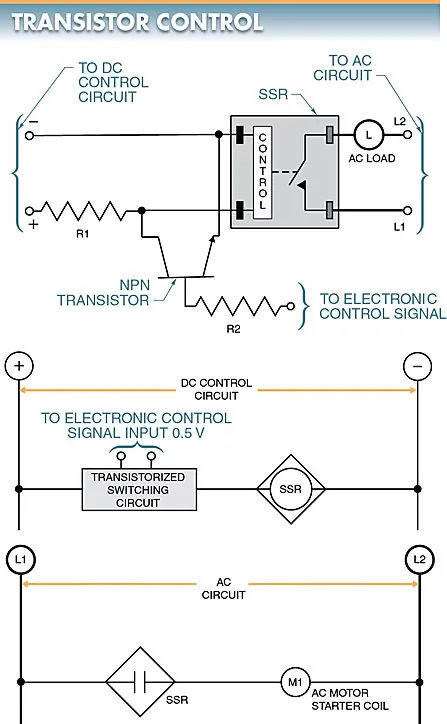
Electronic control signals from logic gates and transistors can also be used to activate solid-state relays. Refer to Fig. 6.
In this circuit, an NPN transistor is used to control the SSR, and it is signaled by various IC logic gates and the like. A pair of resistors (R1 and R2) are used to set a maximum current through the circuit.
Series and Parallel Control
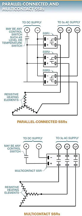
Connecting solid-state relays in series or parallel allows for the creation of multi-contacts that are managed by a single control source. Multi-contact SSRs are also a viable option.
When the switch is closed, all three inputs can be connected in parallel to the SSR’s control output. See Figure 7. This controls the 3φ circuit.
Due to their parallel connection, the DC control voltage across each SSR in this application is identical to the DC supply voltage. One input can toggle multiple output switches on and off with a multi-contact SSR.
A series connection of SSRs can be used to regulate a 3 φcircuit. Figure 8 is displayed below. When the switch is closed, the three SSRs share the DC supply voltage. Since each relay requires a minimum operating voltage of three times its supply voltage, the DC supply voltage must be at least three times that.
