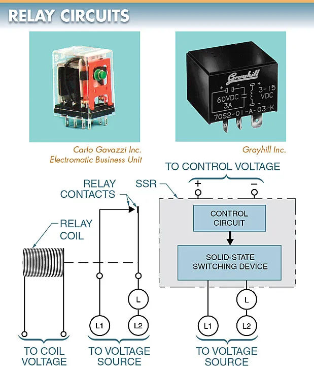
Both solid-state relays (SSRs) and electromechanical relays (EMRs) are intended to perform the same switching function. Electronic switchgear (EMR) makes use of electromagnetic devices and contact sets to implement switching. In order to switch without using contacts, an SSR uses semiconductor controlled rectifiers (SCRs) and triacs.
In addition, EMRs and SSRs have distinct operational and physical characteristics. Refer to Figure 1.

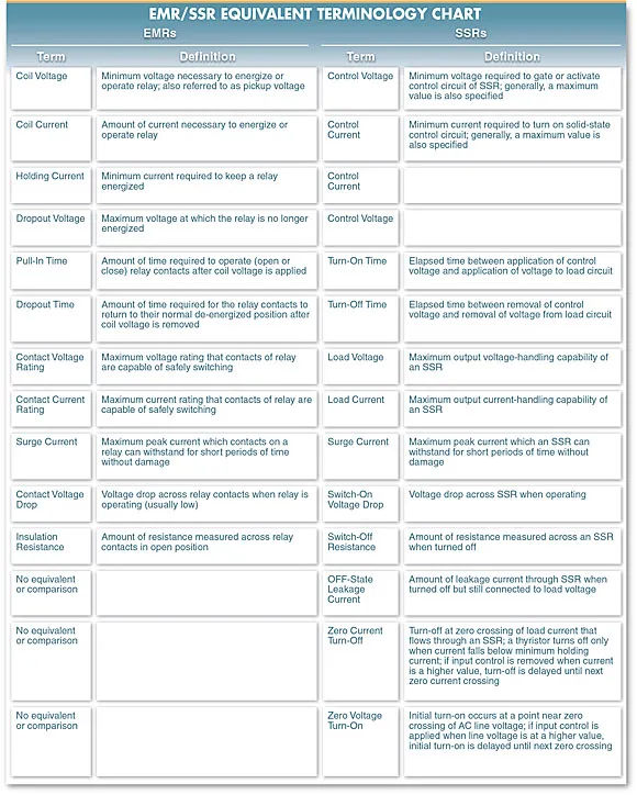
When contrasting electronic medical records (EMRs) and standard medical records (SSRs), a chart of corresponding terms is helpful. It is challenging to find an exact comparison between the two devices due to the fundamental differences in their operation and physical construction.
Almost immediately, you’ll notice differences in how the devices are described and what they’re capable of doing. Please refer to Figure 2.
Advantages and Limitations
It’s not uncommon to find both electromechanical and solid-state relays in use. The electrical needs, budget constraints, and expected service life of the application all factor into choosing the appropriate relay.
Although SSRs have largely supplanted EMRs in many contexts, the latter are still widely used. Because of their many benefits, electromechanical relays are reasonably priced. They can only be used for so many things due to their limitations, though.

Some benefits of an electromechanical relay include:
- typically employ contact configurations with a greater number of poles and throws.
- Both alternating current and direct current (DC) can be switched by the contacts.
- low starting price.
- very small voltage drops across the contacts; eliminating the need for a heat sink.
- highly tolerant of voltage fluctuations.
- There is zero leakage through open contacts when the device is turned off.
The following are some of the drawbacks of electromechanical relays:
- because of normal wear and tear, the useful lifespan of contact lenses is finite.
- contact life is reduced significantly under high switching rates and high current loads.
- cause electromagnetic interference and noise on power lines.
- not very efficient at switching high inrush currents.
Small, fast, long-lasting, and able to handle complex switching needs, SSRs have many benefits. However, there are limitations to SSRs that prevent them from being used in all situations.
There are a number of benefits to using a solid-state relay.
- extremely durable if used correctly.
- There are no necessary contacts for use.
- No EMI is produced due to contact arcing.
- since there are no moving parts, they are resistant to shock and vibration.
- rationale that can communicate with computers, digital circuits, and programmable controllers.
- capable of rapid switching.
- a variety of modes of switching (zero switching, instant- on, etc.).
A few of the drawbacks of solid-state relays are as follows:
- One contact per relay is the norm.
- Voltage drop across switch necessitates a heat sink.
- only accepts either alternating current (AC) or direct current (DC).
- leakage current in the OFF position with the switch open.
- Typically, only a small range of frequencies, say 40 Hz to 70 Hz, can be switched.
Input Signals
By applying current to the input coil of an electromagnetic device, an electromagnet is produced, which can then be used to draw in an armature that has a contact set attached to it, thereby regulating the circuitry of a load. Due to the initial air gap between the magnetic coil and the armature, more voltage and current are required to pull in the coil than are required to maintain its position.
Coil voltage, coil current, holding a current, and drop-out voltage are the parameters used to describe the activation and deactivation of an electromagnetic device.
To activate, a solid-state relay needs only a small amount of voltage and current, as it lacks a coil and mechanical contacts. An SSR’s input signal must be described in terms of both control voltage and control current.
Due to the SSR’s electronic design and input circuit’s digital controllability, the two are easily compatible. Modern logic circuits can benefit greatly from the availability of SSRs with control voltages as low as 3 V and control currents as low as 1 mA.
Response time
A solid state relay’s faster reaction time is a major benefit over electromechanical ones (ability to turn on and turn off). Unlike an EMR, which can only respond a few hundred times per minute, an SSR can toggle between states thousands of times per minute with no chatter or bounce.
The SSR’s DC switching time is microseconds. When using zero-voltage turn-on, the AC switching time for an SSR is less than 9 milliseconds, a significant advantage over the time required to pull in and drop out an electromagnetic relay.
The increased importance of the faster speeds offered by solid state relays can be attributed to the rise in the demands placed on processing equipment by the industrial sector. Equipment efficiency is measured by how quickly it can process or cycle its output.
Voltage and Current Ratings
There are limits to the amount of voltage and current that can be safely handled by both electromechanical and solid state relays. Values can change from device to device and even from manufacturer to manufacturer. Checking a device’s datasheet is the only way to know for sure if it can switch a specific load safely.
SSRs can be used in potentially explosive environments because they are totally enclosed, have no moving parts, and can switch without producing an arc.
If an EMR experiences an excessive surge current, the contacts can be replaced. If something happens to an SSR, the whole thing needs to be replaced.
Voltage Drop
With the exception of pitted or corroded contacts, the contact resistance of a closed set of electromechanical relay contacts is typically quite small. An SSR, however, is made out of semiconductor materials, so it can either open or close a circuit by increasing or decreasing the conductivity of the materials involved.
Even at full conduction, the residual resistance of a solid-state relay can cause a voltage drop in the load circuit of up to about 1.5 V. Since this voltage drop is negligible in comparison to the load voltage, it typically causes no issues. With low load voltages, this special quality may need to be taken into account.
When operating at higher load currents, it is necessary to employ a means of dissipating the heat generated by the switching device.
Insulation and leakage
An open circuit has almost infinite resistance because no current can flow through the air between the contacts. Solid state relays, due to their design, offer a high but measurable resistance when they are switched off. Switched series resistors, or SSRs, feature an inactive resistance not present in EMRs.
Even when an SSR is turned off, a small amount of current can still flow through it (known as “OFF-state leakage”). Leakage current in the OFF state is not observed on EMRs.
When an SSR is turned off, a small amount of current (2 mA to 10 mA) continues to flow through it. As a rule of thumb, an SSR’s output leakage current rating should not be higher than 200 mA at 200 VDC across the output when in the OFF state.