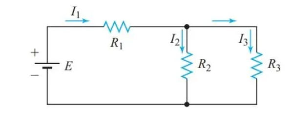
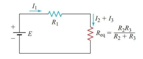
Overall, the circuit in Figure 1 is neither series nor parallel. However, R2 and R3 have the same voltage drop requirements because they are connected between the same two points in the circuit. Since they’re connected in parallel, we can treat them as if they were a single resistor and determine their combined equivalent resistance.
When compared from the voltage source’s terminals, the simplified circuit in Figure 2 is equivalent to the complex one in Figure 1. According to the diagram, R1 is connected in series with the parallel resistances R2 and R3. As a result, the circuit depicted in Figure 2 can be solved as a straightforward series circuit.
R2 and R3 in Figure 3(a) are in series because they both receive the same amount of current. As shown in Figure 3, we can swap them out for a similar resistor (b). This allows us to treat the simplified circuit in Figure 3(b) as a standard parallel circuit and solve it as such.

Series-Parallel Circuit Definition
When some parts of the circuit behave like standard series circuits while other parts behave like standard parallel circuits, we say that the circuit is series-parallel.
Series-Parallel Circuit Solution using Equivalent-Circuit Method
By substituting the equivalent resistances for various portions of the circuit until the original circuit is reduced to either a simple series or a simple parallel circuit, we can solve series-parallel circuits.
Example 1
Determine the resistance values, current, and power consumption of each resistor in Figure 4’s circuit diagram.
Step 1
Determine the resistance values, current, and power consumption of each resistor in Figure 4’s circuit diagram.

Step 2
Since R2 and R3 are in parallel,

The total resistance of the circuit is

Step 3
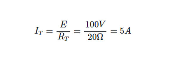
From Ohm’s law,
Step 4
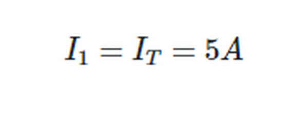
Since R1 is in series with the source,
Step 5
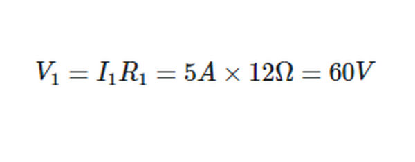
Applying Ohm’s law to R1,
Step 6
From Kirchhoff’s voltage law,

Returning now to the original circuit,

Step 7
Applying Ohm’s law to R2 and R3,
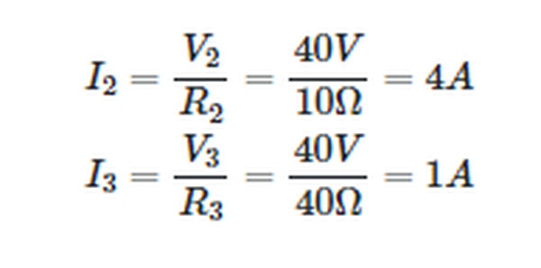
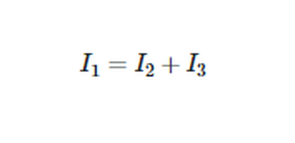
As a final step in checking our work, we can see if the currents we determined comply with Kirchhoff’s current law for this circuit:
Step 8
Since,
P = VI
So,
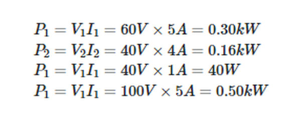
The following checks will allow us to confirm our calculations:
PT = P1+P2+P3
Voltage-Divider Principle
The Kirchhoff voltage law states that E = V1 + V2 + V3 for the series circuit depicted in Figure 5. That is to say, the total voltage applied is split between the three resistors. Six different configurations of terminals A, B, C, and D allow us to use a voltmeter, as shown in Figure 5. Because of this, a voltage divider is produced by connecting R1, R2, and R3 in series.
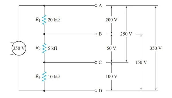
Solving for the six voltages in Figure 5 requires us to first determine RT, then determine I using Ohm’s law, and finally determine the voltage drop across each resistance using the formulas V1 = IR1, V2 = IR2, and so on. Each voltage, however, can be determined in a single procedure. Often referred to as the “voltage-divider principle,” this is a characteristic of circuits connected in series.
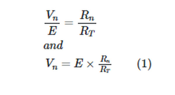
In a series circuit, the ratio between any two voltage drops equals the ratio of the two resistances across which these voltage drops occur.
Hence, for any resistor Rn in a voltage divider,
Example 2
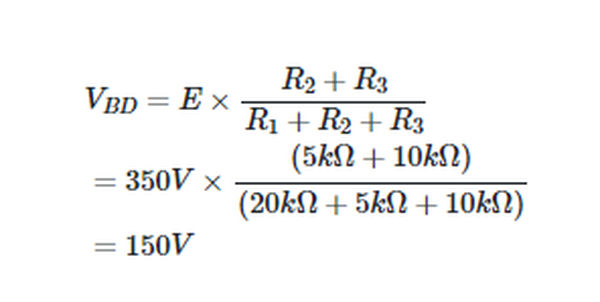
Determine the potential difference between the circuit’s terminals B and D in Figure 5.
Solution
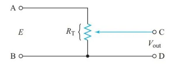
An example of a voltage divider that makes use of a variable resistor is depicted in Figure 6; the terminal voltage of this divider is continuously variable.
Voltage Dividers
In order to reduce the cost, size, and weight of equipment, voltage dividers are commonly used in power supplies for electronic circuits. This allows a single voltage source to supply all the different voltages required by the equipment.
The easiest way to achieve the necessary voltage drop across a specific circuit element is with the series-dropping resistor shown in Figure 7.

Example 3
An electronic component has an operating voltage of 15 V and a current of 20 mA. If the voltage at the supply terminals is 25 V, what value of series-dropping resistor is needed?
Solution
We can use Ohm’s law to visualize this load circuit as a resistor, as shown in Figure 7.

The voltage drop across the series-dropping resistor can be calculated using Kirchhoff’s voltage law.

Being in series with the dropping resistor and the load
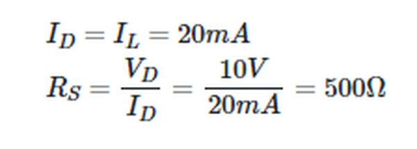
The final step in the design process is to determine the bare minimum power consumption required by RS.

One that is less likely to fail is a 0.5-W resistor because it can maintain its function at lower temperatures than a 0.25-W resistor.
The only draw on the power source is the current through the load, which is why a simple series-dropping resistor is preferable. However, this circuit has the drawback that the voltage supplied to the load and the voltage drop across the series-dropping resistor are both affected by changes in load resistance.
When a transistor is used as the load in a circuit, RL can skyrocket. It is possible that the transistor will be damaged because the voltage across the load will be close to the full applied voltage while the voltage across the series-dropping resistor will be close to zero.
Some voltage-divider designs, like the one shown in Figure 8, incorporate a bleeder resistor in parallel with the load to prevent this kind of damage. Having a bleeder resistor guarantees a constant current through the series-dropping resistor, keeping the voltage drop across it constant. Therefore, the voltage across the load cannot exceed the supply voltage.
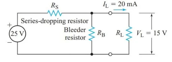
A bleeder current equal to 10–25% of the total current drawn from the source is typically used to protect electronic equipment’s power supplies from overvoltage spikes caused by increasing load resistance.
If the bleeder current is high enough, the load voltage will be less sensitive to fluctuations in the load current. In this way, better voltage regulation is achieved at the expense of additional current drain from the source and additional heat produced in the voltage-divider resistors.
Voltage regulation is more important than a little bit of extra bleeder current when designing voltage dividers for loads consisting of a single transistor.
As multiple voltages can be drawn from the same power source by the same circuit, it is helpful to have a standard voltage reference point.
A common practice is to connect the circuit to the metal chassis it is housed in. Sometimes the electrical system’s ground wire will also connect the chassis to the ground.
Figure 9’s bottom symbol conveys the message that the axis is firmly planted on the ground. Given this, we can say that point A has a voltage of 1250 V relative to ground. Connecting the chassis to the circuit is represented by the middle symbol in Figure 10.
At point A in this circuit, the voltage is 112 V relative to the chassis, while at point B, the voltage is 212 V.

Many electronic circuits employing transistors necessitate either positive or negative voltages with respect to a shared chassis connection. With the tap of a voltage divider connected to the chassis, as shown in Figure 10, we can obtain both positive and negative voltages from a single power source.
Example 5
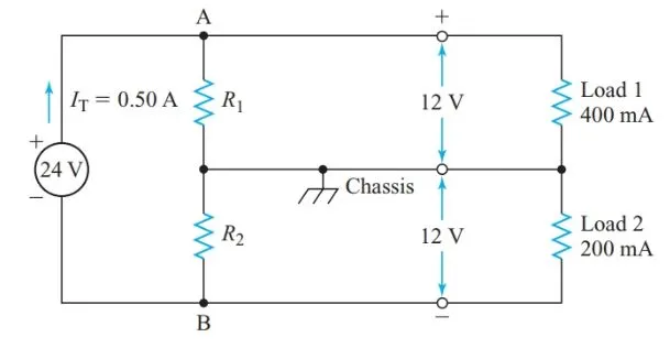
Figure 10 depicts a power supply with a terminal voltage of 24 V DC at full load. Determine the current drains at 112 V and 212 V, and then design a voltage divider to supply 112 V and 212 V, respectively, relative to the chassis. A total of 500 mA is drawn from the power supply.
Solution
As R1 is connected in series with the first load, V1 will be 5 V. Using the most up-to-date version of Kirchhoff’s law at A,
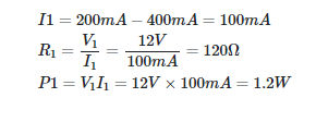
Similarly
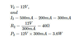
Current-Divider Principle
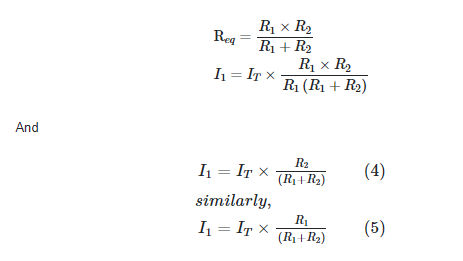
The current-divider principle can be described as:
In a parallel circuit, the ratio between any two branch currents equals the ratio of the two conductance through which these currents flow.
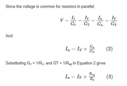
Hence, we can restate the current-divider principle:
In a parallel circuit, the ratio between any two branch currents is the inverse of the ratio of the branch resistances.
For two resistors in parallel,
Example 6
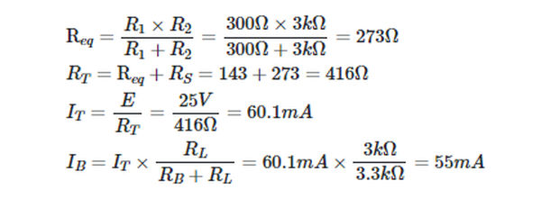
If the load resistance is 3.0 k, as shown in Figure 11, then determine the bleeder current in the voltage divider.

Solution
Paralleling the bleeder resistor with the load resistance yields an equivalent resistance of
Cells in Series-Parallel
If you connect multiple batteries in series and parallel, as shown in Figure 12, you’ll get more power out of the system as a whole. Because of the potential for internal battery currents to circulate, it is imperative that all of the cells be identical. Number of paralleled rows determines overall battery capacity.
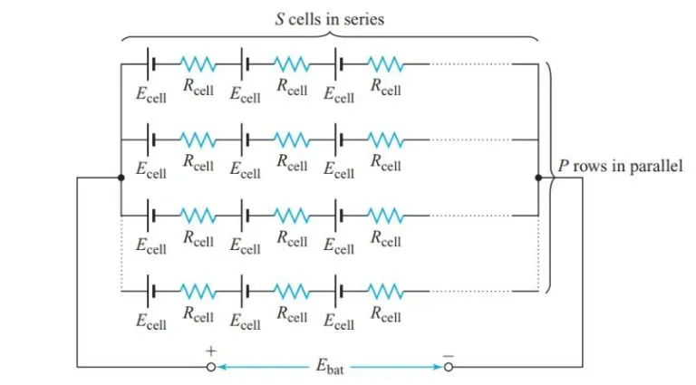
In a battery with P parallel rows and S series-connected cells, the battery’s electromotive force (EMF) is equal to the EMF of a single series-connected row.

Internal resistance is the sum of the resistances of P rows of S identical resistors, each of which has a resistance of Rcell in isolation.

Example 7
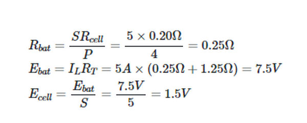
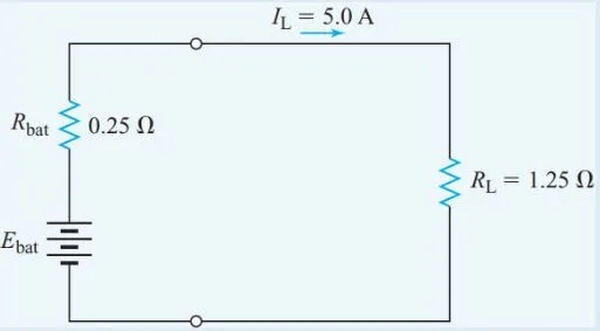
A total of twenty identical cells are linked together in four rows of five cells each. The resistance of each cell is 0.20 V. According to Figure 13, a battery can supply a current of 5.0 A to a 1.25 V resistor. Get the EMF for each individual cell.
Solution
