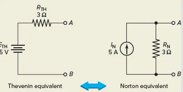
With the help of Norton’s theorem, a network can be reduced to a few simple nodes by focusing on currents rather than voltages. This theorem applies equally well to single-source and multi-source circuits. The analysis of current distributions may be simpler than voltage analysis in some situations.
By applying the Norton Equivalent Current Source (IN) and Norton Equivalent Resistance (RN) shown in parallel in Figure 1, Norton’s theorem reduces the complexity of a resistive network.
Norton’s theorem is based on the distribution of a total load current among parallel branches, which is supplied by a current source.

Norton’s Equivalent Circuit
In the same way as with related theorems, you need to follow a specific procedure to get to an equivalent circuit. If you want to know how to turn a resistive network into its Norton equivalent circuit, here are the steps you need to take:
- Find out the Norton equivalent current source. If the load resistor were removed and replaced by a short circuit, the current that would flow between terminals A and B would be the same as this value.
- Work out the equivalent Norton resistance. That’s the same as the resistance you’d get if you created a short circuit between terminals A and B when the power was turned off.
Norton’s Equivalent Circuit Example 1
Create the Norton equivalent circuit for the resistive network shown in Figure 2. Please determine the current and voltage at the 6-Ω load resistor RL. Simply substitute a 3 Ω resistor as the load in your calculations.
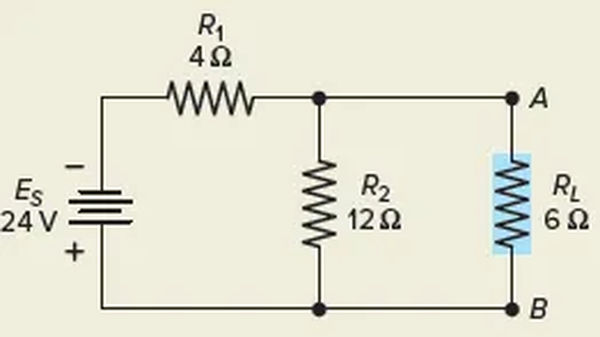
Solution:
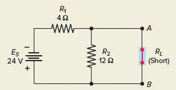
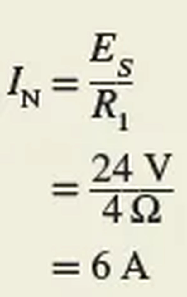
First, connect the load terminals A-B in a series as shown in Figure 3. Determine how much current will flow as a result. This is the value of the current source IN that is the Norton equivalent. Keep in mind that the parallel R2 is also shorted out by the short across terminals A-B. When only R1 is connected in series with the power supply, the circuit has no other resistance.
With the load removed and the voltage source replaced by a short circuit, as shown in Figure 4, the resistance between terminals A and B is equal to the Norton equivalent resistance (RN). With A and B as terminals, the resistance seen from the other side of the circuit is R1 in parallel with R2.
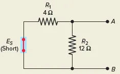
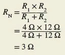
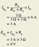
Connect the load resistor to the equivalent Norton circuit, as shown in Figure 6, to determine the IRL and ERL. The 6 A of current from the source is still being delivered, but it is now being shared between the RN and RL conductors. One can determine the load current by using the current divider rule, and the load voltage by applying Ohm’s law.
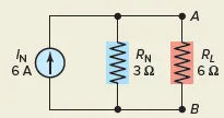
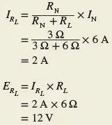
In the fifth step, if you alter RL but keep IN and RN the same, you’ll end up with the same result. It is possible to determine the current and voltage through a 3-Ω load without having to redo the entire circuit calculation.
Norton’s Equivalent Circuit Example 2
Figure 7 is a resistive network; please determine its Norton equivalent circuit.
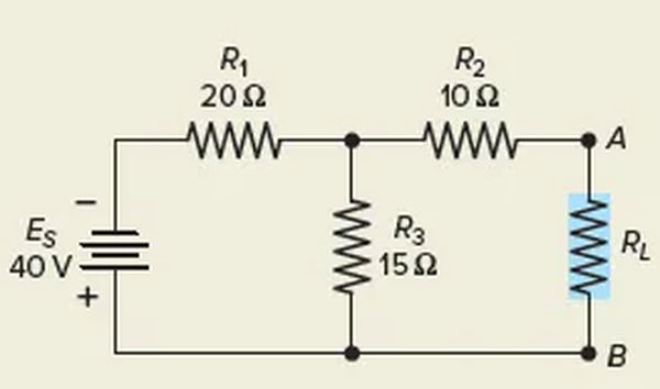
Solution:
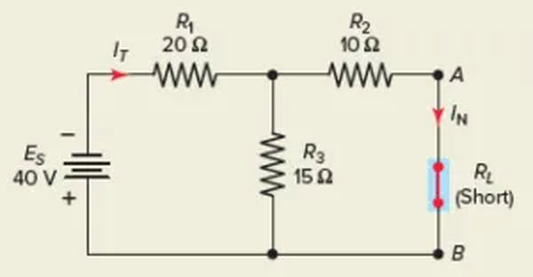
Step 1. Short-circuit the load, as shown in Figure 8, to determine the Norton equivalent current. Note that the short circuit current IN in this example is a branch current, not the main line current. Resistors R2 and R3 are now in parallel so the total resistance seen by the voltage source is
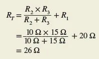
The total current is then

The current divider rule is then applied to determine the Norton equivalent current:
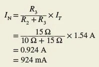
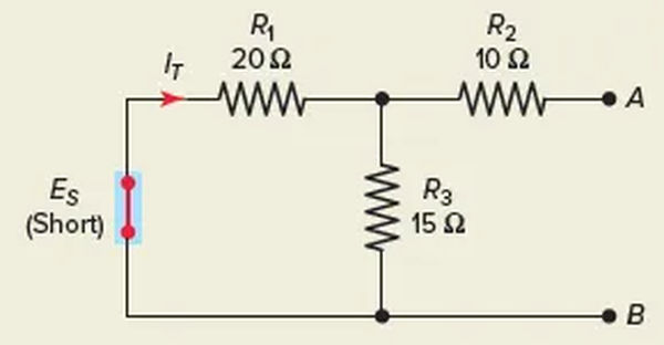
Step 2: Determine the Norton equivalent resistance by short-circuiting the voltage source, as shown in Figure 9. It is now true that R1 and R3 are in parallel, and that R2 is connected in series with this parallel combination.
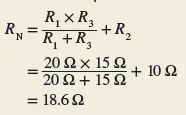
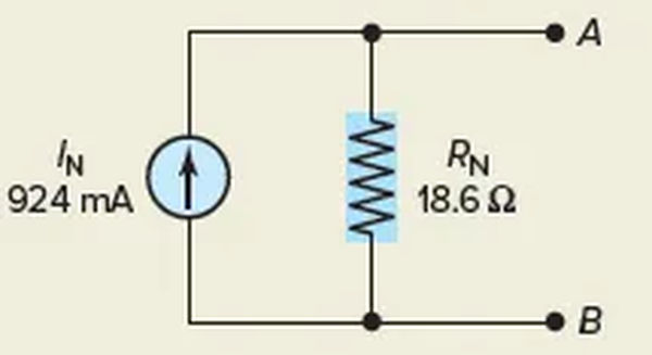
Step 3. After that, you can draw the Norton equivalent circuit as shown in Figure 10.
It is possible to derive the Norton equivalent circuit from the Thevenin equivalent circuit, and the other way around. The connection between the two circuits is depicted in Figure 11. Using the following equations, you can change one equivalent circuit into another:
From Thevenin to Norton

From Norton to Thevenin

