A DC generator’s components and operating principle are broken down and illustrated in this guide.
A direct current (DC) generator is a device that uses electromagnetic induction to transform mechanical energy into electricity. For DC generators to work, the wire coil must be rotated while immersed in a magnetic field, which induces a voltage in the coil. The rate at which the coil is rotated in a magnetic field determines the magnitude of the voltage induced in the coil.
The voltage induced in a coil as it is rotated at a constant speed in a magnetic field is proportional to the density of the magnetic field at any given moment. The components of a DC generator are the field windings, armature, commutator, and brushes. Refer to Figure 1.

Field Windings
In a DC generator, the magnetic field is created by field windings, which are electromagnets. Permanent magnets or electromagnets can generate the magnetic field that powers a generator.
The tiny machines known as magnetos rely on permanent magnets. One drawback of permanent magnets is that the strength of their magnetic lines of force declines over time.
The inability to adjust the magnetism of a permanent magnet is another drawback.
The majority of generators rely on electromagnets, which require an electrical current to function.
The generator is said to be “separately excited” if it requires an external source (such as a battery or another DC generator) to supply the current for the field windings. A generator is said to be self-excited if it generates the current needed to power the field windings. In most cases, DC generators will provide their own source of excitement.
Armatures
In a generator, the armature is the coil of wire that can rotate in response to the magnetic field. The armature of a DC generator spins, but the field remains still (field windings). The armature that spins around could have numerous coils. Increasing the number of coils helps smooth out the output voltage, but it’s still not possible to eliminate the ripples entirely.
Commutators
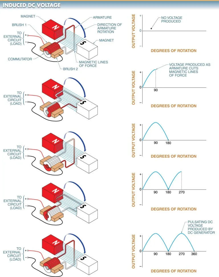
A commutator is an insulating ring with separate sections. A wire coil with a connection at each end. When a coil crosses a magnetic field’s lines of force, a voltage is induced in the coil. Refer to Figure 2.
At the halfway point, the commutator segments switch which brushes are connected to which segments. Therefore, the DC generator’s output voltage will always be of the same polarity.

Brushes
To make electrical contact between the armature and the outside world, an armature uses a brush, which is a sliding contact that rides against the commutator segments or slip rings.
Soft carbon is used to create brushes (natural graphite). The brushes are more delicate than the commutator bars, but they are nonetheless robust enough to withstand vibration without chipping or breaking. There is a single point of contact between the brush and the commutator segments.
When the current through a DC generator is zero, the brushes will move along the commutator’s individual segments. As a result, there is a constant unidirectional flow of current in the external circuit (load), albeit with a continuously changing magnitude.
Commutation refers to the process by which a direct current is achieved by switching the polarity of the connections to the coil (armature). A DC generator produces a DC voltage that pulses as its output. The ripples in the output voltage are the pulsations in the voltage.
Left-Hand Generator Rule
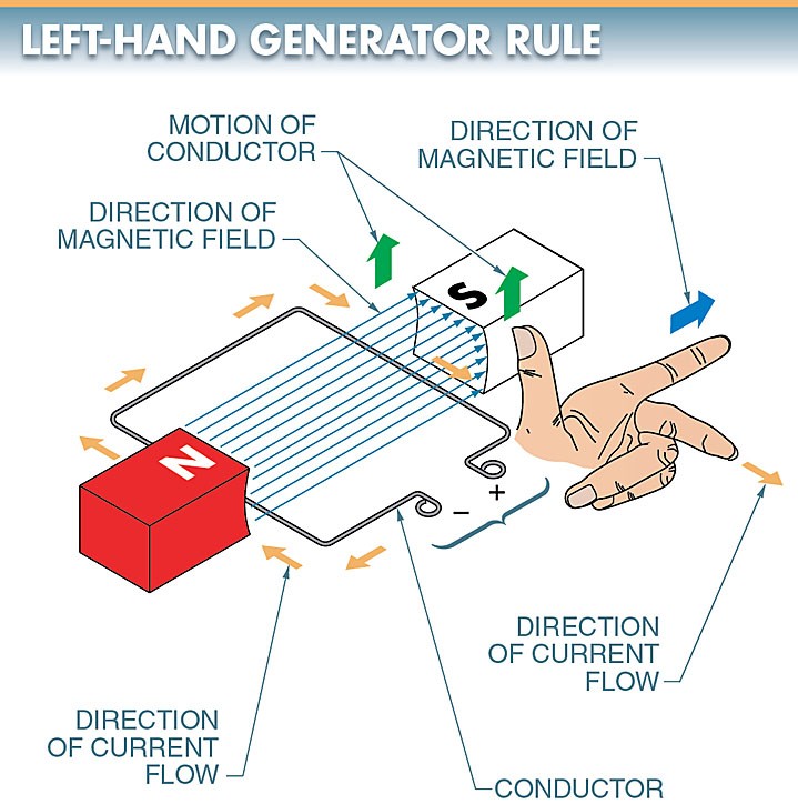
Current in a conductor and the surrounding magnetic field are related according to the left-hand generator rule.
The left-hand generator rule states that with the thumb, index finger, and middle finger of the left hand set at right angles to each other, the index finger points in the direction of the magnetic field, the thumb points in the direction of the motion of the conductor, and the middle finger points in the direction of the induced current. See Figure 3.
It is assumed that the magnetic field is fixed in place and the conductor is moving through it when applying the left-hand generator rule.

To prevent current from flowing back to the generator from the batteries while using a DC generator to charge them, a diode can be placed in series with the generator and batteries.
When the voltage of the generator falls below that of the batteries, a current flows from the batteries back to the generator. By draining the batteries, the current sent to the generator drives the DC generator.
