There is a standard set of symbols and conventions for drawing line diagrams (circuits) that are used throughout the electrical industry. By following these guidelines, electricians can create a standard method of operation and a shared vocabulary.
One Load per Line
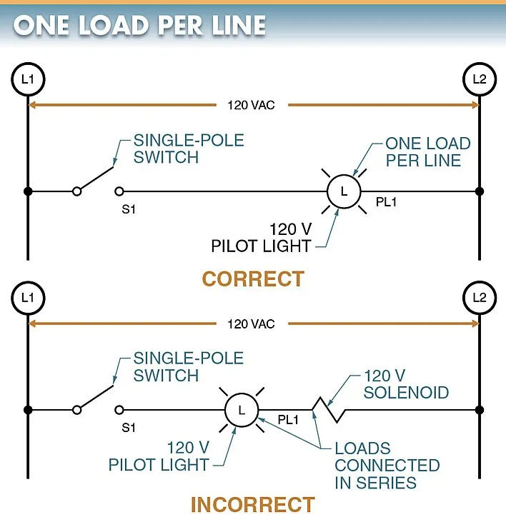
Between L1 and L2’s power sources, no single circuit line should carry more than one load. In order to wire a pilot light into an existing circuit, all you need is a single-pole switch. Refer to Figure 1. The power lines (labeled L1 and L2) in this circuit are drawn vertically along the sides of the paper. The control circuit voltage is indicated by the gap between L1 and L2. When switch S1 is engaged, this voltage appears across pilot light PL1. The voltage between L1 and L2 is ideal for the pilot light, so the light turns on when current flows through S1 and PL1.
No two loads may be connected in series along the same line in a circuit diagram. When S1 is closed and the two loads are connected in series, the voltage between L1 and L2 must be split between them. As a result, only one of the two devices is getting the full 120 V it needs to function.
The voltage drops the most when passing through the load with the highest resistance. The voltage drop is minimized in the load with the lowest resistance.
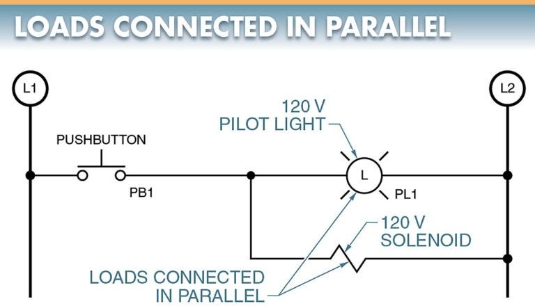
In a line diagram, multiple loads are always connected in parallel. Refer to Figure 2. Even though there are two loads in the circuit, only one is connected to each line between L1 and L2. For the pilot light and solenoid to work properly, voltage must appear across each load from L1 and L2. A pilot light line and a solenoid line are included in this circuit.
Load Connections
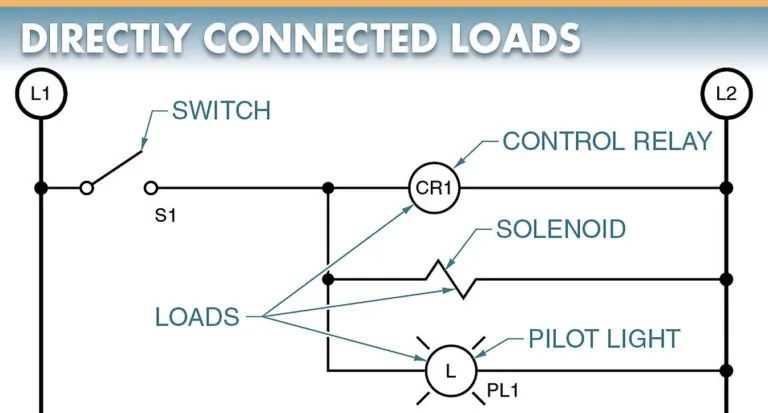
Anything that uses electricity to create mechanical motion, thermal or visual effects, or audible tones is considered a load. In a circuit diagram, a load is any appliance connected between L1 and L2 that consumes electricity. Direct or indirect loads connected to L2 include relay coils, solenoids, and pilot lights. View Figure 3.
Overload contacts are normally closed (NC), which allows a magnetic motor’s starter coils to be connected to L2 in an indirect fashion. For evidence, see Figure 4.
Overload contacts are normally closed and will only open if the motor is experiencing overload. Depending on the type of starter and the circuit’s power, a different number of NC overload contacts may be required between the starter coil and L2.
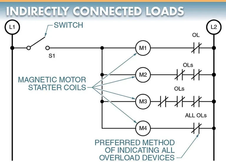
Line diagrams can include anywhere from one NC overload contact at the starter to three at L2. As shown, starters can have anywhere from one to three NC overload contacts, depending on the manufacturer and the motor being used.
Typically, there would be three overload contacts in an older starter, one for each of the starter’s heaters. Only one set of overload contacts is necessary in a modern starter.
To keep things simple, it is common practice to designate all overloads as being connected to the same set of NC overload contacts (OLs). As long as the motor and starter are compatible with the marked overload, the circuit is good to go. If more than one NC overload contact is present on the starter, the electrician knows to connect them in series.
Control Device Connections
Devices for regulating power are wired between L1 and the power coil (or load). Pushbuttons, limit switches, and pressure switches are some examples of control devices used to activate the operating coils of contactors and starters. Observe the fifth figure.
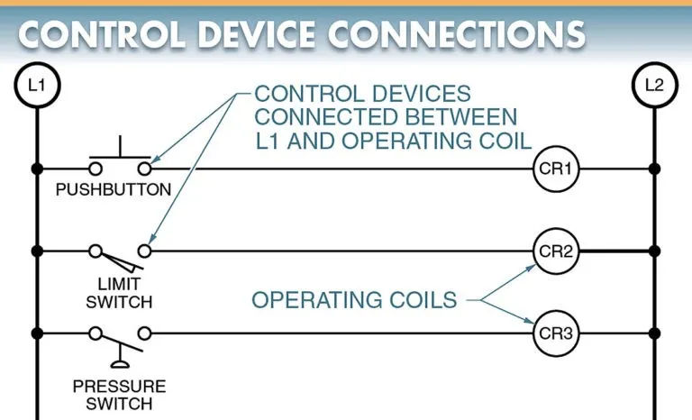
The lines are regulated by at least one device. If a line does not have a control device, the operating coil remains permanently switched on.
The number of control devices in a circuit is not limited so long as they are sufficient to achieve the desired operation of the coil. When controlling a coil of some sort, these controllers can be wired in either series or parallel.
In spite of the fact that any number of loads can be included in a circuit, the total number of loads is what determines the necessary wire size and rating of the incoming power supply (typically a transformer). When more loads are connected to a circuit, the total current rises.
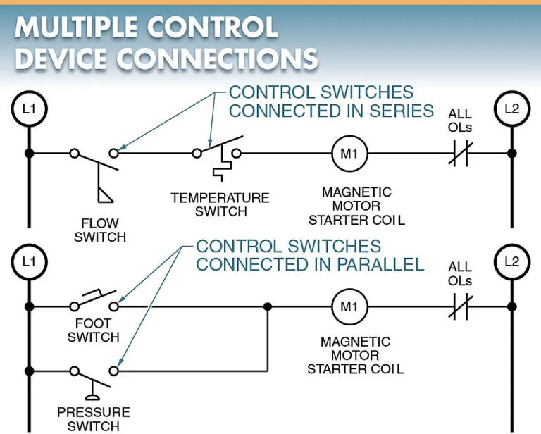
A magnetic motor starter’s coil can be controlled by a combination of two control devices (a flow switch and a temperature switch) wired in series. For current to flow from L1 through the control device, the magnetic starter coil, and the overloads and into L2, the flow switch and the temperature switch must close. Notice in particular Figure 6.
A magnetic motor starter’s coil can be controlled by two separate devices when connected in parallel: a pressure switch and a footswitch. Take a look at the diagram in Figure 6.
In order to allow current to flow from L1 through the control device, the magnetic starter coil, and the overloads to L2, either the pressure switch or the footswitch must be closed. It doesn’t matter how the circuit’s control devices are laid out, they must all be linked between L1 and the operating coil (or load).
Normal Open (NO) or Normal Closed (NC) contacts can be used for the control device (NC). The function of a circuit is determined by the contacts used and the way the control devices are connected (in series or in parallel).
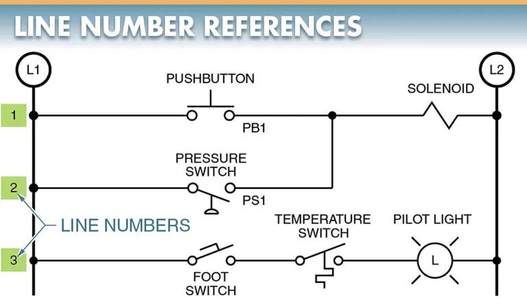
Line Number References
Number the lines in a line diagram from highest to lowest, starting at the top. Please refer to Figure 7.
Complete the circuit between L1 and L2 by joining PB1 to the solenoid with Line 1.
Line 2 completes the circuit between L1 and L2 by linking power supply 1 (PS1) to the solenoid. Since the path from L1 to L2 is finished by either the pushbutton or the pressure switch, these two lines are marked as distinct even though they both control the same load.
Complete the circuit between L1 and L2 with Line 3, which links a footswitch and a temperature switch. In this case, the footswitch and the temperature switch are on the same line because turning on the pilot light requires both of them.
To better comprehend a circuit’s operation, line numbers should be included. As more lines are added to a circuit, the significance of this numbering system becomes more apparent.
