Most electricity is delivered to consumers today from large, centralized power plants through a system of transmission lines (conductors), substations (transformers), and generating equipment.
These massive, centralized power plants are situated close to readily available fossil fuels like coal, oil, and natural gas. Additionally, large, centralized power plants tend to be situated in close proximity to their respective sources of raw materials. Nuclear power plants, for instance, typically need to be situated close to sizable bodies of water for the purpose of cooling the reactor.
The electricity generated at a large, centralized power plant must pass through a number of transmission and distribution systems before it reaches the loads.
The organization that produces and/or distributes electricity to customers is normally referred to as a utility.
Utilities, however, are reorganizing their internal structures to separate their various functions into distinct business models, such as electricity generation and distribution.
Centralized Power Transmission and Distribution
Distribution of electricity generated at a single, large facility is referred to as “centralized power distribution.”
To ensure reliable service, the entire transmission and distribution network, from the power plant to the end users’ appliances, must be regularly checked and serviced. For an example of this, please refer to Figure 1.
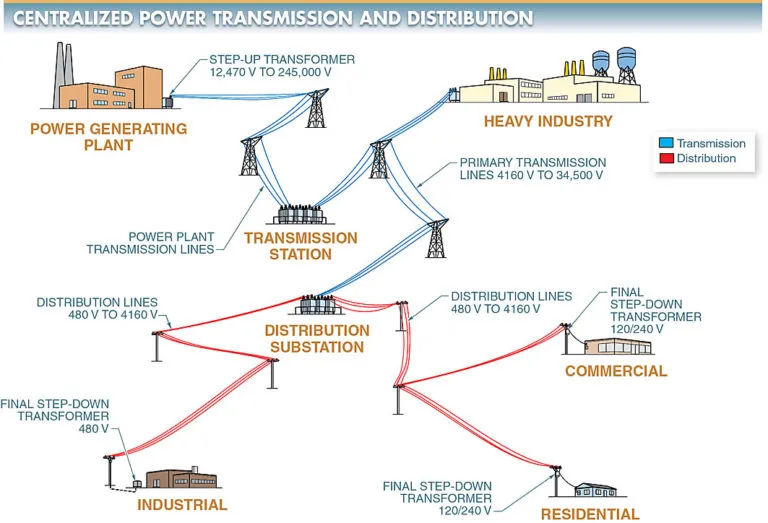
Power transmission is the process of delivering electrical power from a power-generating plant to a substation.
Power distribution is the process of delivering electrical power from a substation to the customer’s service-entrance equipment.
Electrical power delivery necessitates control, protection, transformation, transmission, distribution, and regulation. The following components are typically found in a centralized electrical transmission and distribution system:
- Transformers that “step up” the voltage from generators to transmission standards. The standard range for transmission voltage is between 12.47 kV and 245 kV.
- Power is transmitted from the generating stations to the transmission substations via transmission lines ranging in voltage from 12.47 kilovolts (kV) to 245 kV.
- At transmission substations, the primary (feeder) voltage is lowered. Normal operating range for the primary voltage is between 4.16 kV and 34.5 kV.
- Power is transmitted from generation plants to distribution substations and heavy industry via 4,16 kV to 34.5 kV primary transmission lines.
- In distribution substations, high voltage is reduced to safe, usable levels. Voltages from 480 V up to 4.16 kV are used in various applications.
- To get from the distribution substation to the last step-down transformer, wires run along the sides of streets and behind houses.
- Step-down transformers are used as a last resort to reduce the voltage to a more manageable level, typically 480 V or 120/240 V. The last stage of step-down transformers can be set up on poles, on pads at ground level, or in underground vaults. As the last step in the process, the secondary of the step-down transformer is wired into the cables that feed the service entrance. Depending on the power needs of the customer, a specific number and size of transformers will be used to step down the voltage before it is used by the customer’s power distribution system.
Transmission Lines and Towers
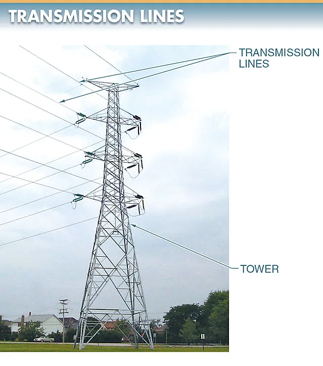
Electrical power is transmitted along transmission lines, which are conductive cables capable of handling high voltages and large currents over great distances. Refer to Figure 2. Transmission lines in the air need to be kept safely apart and at a safe height.
Depending on the distance to be traveled and the amount of power to be transferred, different transmission voltage levels are used. There will be more voltage transmitted if the distance is greater or if more power is being sent.
It is estimated that between 6 and 7 percent of the electrical power generated each year is lost as heat during transmission and distribution.
The voltage along a transmission line can range from a few tens of kilovolts to hundreds of tens of thousands. The current capacity of a transmission line determines the size of the conductors used in that line.
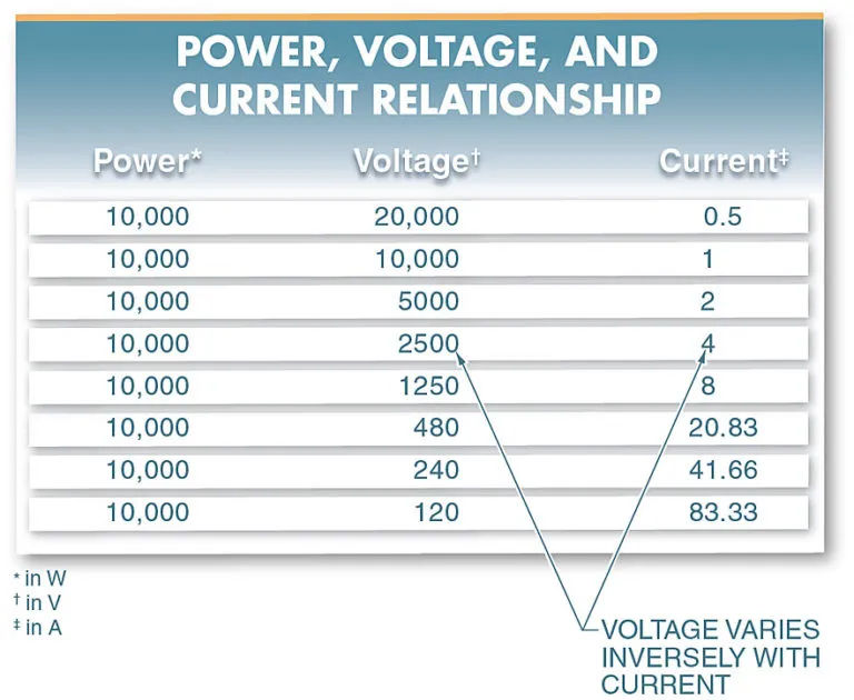
The amount of current varies inversely with the voltage for a fixed amount of power. Examine the illustration in Figure 3. Boosting the voltage being transmitted between the utility and the customer helps to lessen power losses along the transmission path.
When the transmitted voltage is doubled, power loss is cut by as much as 75%. Since less material is needed to transmit power at higher voltages, the conductors can be smaller and lighter. As a result, higher transmitted voltages permit smaller conductor sizes, increase the amount of power that can be transmitted, and reduce the total cost of the necessary materials.
Distribution Substations
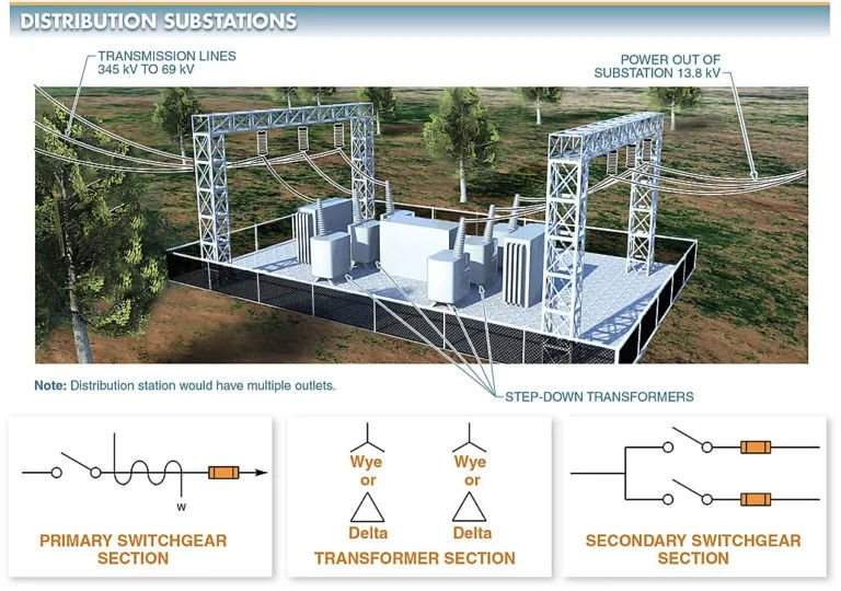
A distribution substation is an outdoor facility used to regulate voltage, centralize switching, monitor and protect the system, and redistribute power to consumers.
Substations used for distribution take the high voltages produced during transmission and lower them to safer levels. The voltages used in distribution substations are typically lower than those used in transmission substations. The voltages that come out of distribution substations typically range from 12 kV to 13.8 kV. Look at Figure 4.
Substations located along the distribution network are responsible for transforming and controlling voltage. These features are included in distribution substations:
- capturing the generated voltage and regulating it for use in transmission or by end users.
- allowing for a point of connection to be changed.
- providing a point in the distribution grid where power can be safely shut off in case of an emergency.
- offering a handy location to conduct distribution system checks and measurements.
The real-time rating of a transmission line is the maximum current at which it can safely operate. Real-time ratings for transmission lines are dependent on factors like wind speed, ambient temperature, and solar radiation. The maximum current that can be transmitted without breaking safety regulations, reducing network reliability, or damaging equipment is determined by this rating. When the live current is higher than the rating, the conductors heat up, causing the line to sag and the resistance to rise.
Distribution Substation Components
Primary switchgear, secondary switchgear, and transformers make up the three main parts of a distribution substation.
The substation’s primary or secondary switchgear, respectively, may be its high- or low-voltage components, depending on its intended use.
The primary switchgear in a step-up substation is the low-voltage part, while the secondary switchgear is the high-voltage part.
The primary switchgear in a step-down substation is the high-voltage part, while the secondary switchgear is the low-voltage part.
A distribution substation typically also features circuit breakers and interrupter switches.
Power Distribution to Point of Use
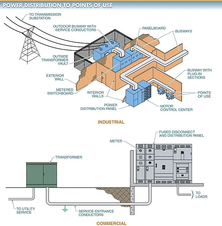
Distribution lines carry electricity from power plants to homes, businesses, and factories. View Figure 5. Switchboards are where these lines are spliced off at the end of their runs to various commercial and industrial establishments.
Switchboards are large pieces of electrical equipment used to divide and switch circuits in a building’s electrical distribution system.
Overcurrent protective devices, electrical meters, and switches are all components of switchboards (OCPDs).
After electricity has been brought into a building, it is distributed to various points using switchboards. Panelboards are used to terminate and distribute electricity to homes.
An utility’s power supply could be either lateral or overhead.
Service entrance conductors for an overhead service are strung from the utility pole directly to the building’s roof.
A service lateral is a type of underground electrical service that connects a building to the utility grid at its service entrance.
A service point connects a building’s electrical system to the utility’s infrastructure. The switchboard is the beginning and ending point for the electrical distribution system in most buildings, depending on how the utility company wires the building.