Electrical circuits can be analyzed in the most comprehensive way using node voltage analysis. In this article we show how it can be used in linear resistive circuits. Each node’s voltage is treated as a separate variable in the node voltage method. The voltages at each of the nodes are expressed with respect to a single node that serves as a reference (typically ground, but this is not always the case).
Each branch current can be written in terms of one or more node voltages thanks to Ohm’s law and the relationship between resistor current and node voltage. In the end, KCL is performed on each node that is not the reference node in order to produce a single equation for the voltage at each node. Since only the node voltages and the known parameters are used, the equations contain only those two pieces of information.
Ohm’s law and the KCL are shown in action in Figures 1 and 2, respectively, of this procedure.
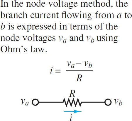
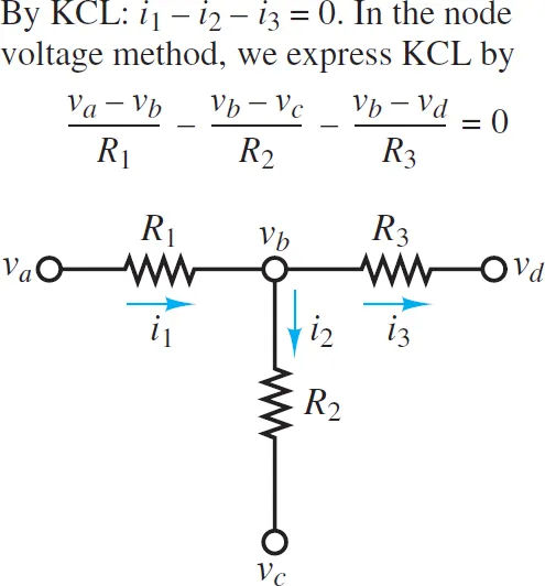
Once the node voltages are known, Kirchhoff’s current law is applied at each node to determine the branch currents:
∑i = 0 (1)
This method, when applied systematically to a circuit with n nodes, yields n1 equations. However, a zero-voltage reference node must be selected, and this can be done at will and with relative ease. A system of n independent linear equations with n+1 variables (the voltages at the nodes) is the end result. The fewest possible equations to solve the circuit are obtained from a node analysis.
Node Analysis Step by Step Guide
- Decide on a node to use as a point of reference. As a general rule, the node with the most children is the one you should use here. Each node’s voltage will be expressed as a percentage difference from the reference node’s voltage, which is typically set to 0 V for ease of use.
- Second, we need to define the voltage variables V1, V2,…, Vn-1 for the remaining n-1 nodes.
- The voltages at each of the n-1 nodes are considered separate variables if there are no voltage sources in the circuit.
- If there are m voltage sources in the circuit:
- Only (n -1) – m voltages can be considered truly independent.
- The voltage varies depending on m factors.
- One of the two voltage variables at an adjacent node (Vj or Vk, for example) must be considered a dependent variable for every voltage source.
- Third, use Kirchhoff’s current law (KCL) at each node corresponding to an independent variable, expressing the voltage across each resistor in terms of the voltages at its neighbors using Ohm’s law. Consistently throughout this book, we will refer to currents entering a node as positive and currents leaving a node as negative. However, the inverse convention is perfectly acceptable.
- There will be an additional dependent equation for every voltage source.
- (e.g., Vk = Vj +Vs ).
- Vj or Vk will be the reference node value, which is typically assigned as 0 V, and the additional dependent equation is especially simple when the voltage source is adjacent to the reference node.
- Compile coefficients for each of the n – 1 variables and use them to solve the n – 1 equations in a linear system.
- It is possible that some of the dependent equations can be written in the form vk=vs. By directly substituting one variable for another, we can reduce the total number of equations and variables involved.
Each and every circuit has a solution that can be found using this method. Solving circuits without voltage sources is a good warmup for the more difficult task of solving circuits with voltage sources. The following paragraphs will continue in this format.
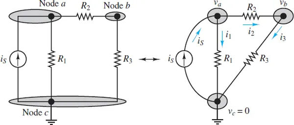
Some readers may find it helpful to see a circuit not as a series of nodes but as a collection of circuit elements connected together in a non-rectangular fashion. In order to build the right side of Figure 3, we first draw three circles to serve as nodes, and then we fill in the space between them with the various components shown. The correct number of nodes must be known in order to successfully redraw a circuit or apply node analysis. Therefore, learning to identify and tally nodes is a valuable skill.
Details and Examples
Take Figure 3’s circuit as an example. It is possible to pick any three directions for the currents i1, i2, and i3, but it is usually wise to pick ones that seem to fit in with one’s preconceptions. Since is is being sent into node a, it stands to reason that i1 and i2 should be sent out of the same node. The node an application of KCL.
is − i1 − i2 = 0 (2)
while at node b
i2 − i3 = 0 (3)
Since the KCL equation depends on the other two, it is not necessary or useful to apply it at the reference node. It could be instructive to use this illustration to show this. Using KCL at node c, we get the following equation:
i1 + i3 − is = 0 (4)
No matter which node you start from, you’ll end up with the same equation. This finding lends credence to what was previously stated:
For an n-node circuit, KCL produces n-1 separate equations. Typically, v=0 is used as the reference in the nth equation.
Currents must be expressed in terms of node voltages when using the node voltage method. Following ohm’s law, we can write i1, i2, and i3 above as va, vb, and vc. The current between points a and c is:

The same holds true for the other two splinter currents.
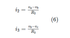
When substituted into the two-nodal equation (equations 2 and 3), these expressions for i1, i2, and i3 yield:

The solutions to equations 7 and 8 can be determined by carefully observing the circuit with some effort. Assuming R1, R2, and R3 are known, we can find the values of va and vb using these equations. It is possible to reformulate the same equations in the following way:

Node Analysis with Voltage Sources
Voltage-supplying circuits are extremely prevalent in the real world. In order to demonstrate how node analysis is used in such circuits, consider the circuit depicted in Figure 4. A total of n = 4 nodes should be found in this circuit, which you must confirm.
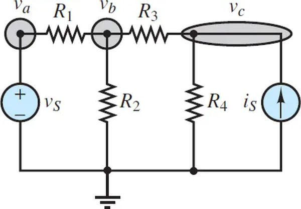
To begin, pick a node to use as a benchmark. As a general rule, the node with the most children is the one you should use here. Each node’s voltage will be expressed as a percentage difference from the reference node’s voltage, which is typically set to 0 V for ease of use.
It is preferable to select the reference node such that at least one of the voltage sources is connected to it when voltage sources are present. The ground node in Figure 5 is assumed to have a voltage of 0 V.
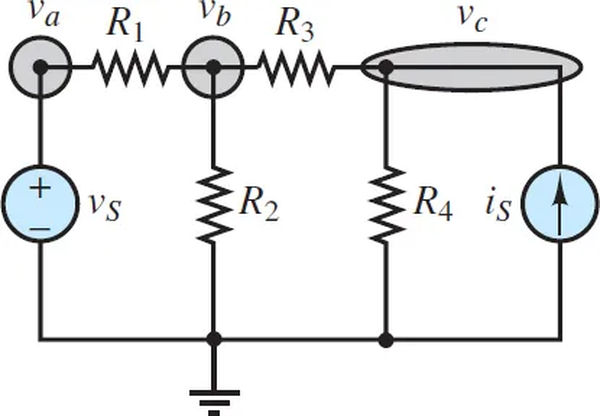
To proceed to Step 2, assign voltage variables (v1, v2,…, vn-1) to the remaining n 1 nodes. If there are m voltage sources in the circuit:
- Only m independent voltages out of a total of (n-1) exist.
- The voltage varies depending on some m.
- One of the two voltage variables at the adjacent node (either vj or vk) must be considered a dependent variable for each voltage source.
As shown in Figure 5, the remaining three (4-1 = 3) node voltages are designated va, vb, and vc. A single voltage source (m = 1) means that there are two independent variables (4-1-1 = 2) and a single dependent variable (m). Va is the only dependent variable because it is in close proximity to the voltage generator.
Use Kirchhoff’s current law (KCL) at every node related to the independent variable, rewriting the voltage across each resistor into terms of the voltages at its neighbors using Ohm’s law. It is assumed that currents entering a node are positive and currents leaving a node are negative.
• There will be one more dependent equation (like Vk = vj + Vs) for each voltage source Vs.
The additional dependent equation is extremely straightforward when a voltage source is located next to the reference node, as either vj or vk will be the reference node value (typically 0 V).
Put KCL into action at the two nodes representing vb and vc:
At node b:

At node c:

Va is defined by the following equation:
va = 0 + vs = vs (10c)
After that, in Step 4, you’ll solve the linear system by accumulating coefficients for all n -1 variables.
n+1-equation system.
- It’s possible that some of the dependent equations can be written as vk = vs. By directly substituting one variable for another, we can reduce the total number of equations and variables involved.
In equation 10a, you should replace va with. In the node b, we have:

The system of two equations can then be written using the gathered coefficients of the two independent variables, as in:

Two equations in two unknowns are the end result, and they can be solved at this point.