Three-phase induction motors, like all motors, have a stator (the stationary part) and a rotor (the moving part) (which rotates). Each has electrical windings that generate a magnetic field when energized. Torque, which is responsible for turning the rotor and the load, is generated by the interaction of magnetic fields. The induction motor shown in Figure 1 is a three-phase model.

Figure 1: Exploded view of a three-phase induction motor construction:
- Fan cover,
- Cooling fan,
- End bell,
- Lifting eye,
- Nameplate,
- Stator kcoils,
- Bearing seal,
- Ball bearing,
- Squirrel-cage rotor,
- Cast-iron frame,
- Wiring box
Stator
The innermost layer of the laminated stator core is fabricated from stamped sheet steel that features slots. Laminations in a stator (and rotor, as shown in Figure 2) In this configuration, three identical windings are arranged in a row of overlapping coils.
Smaller motors have their stator slots partially closed to minimize air gap while larger motors use open stator slots to accommodate the larger pre-shaped and insulated coils.
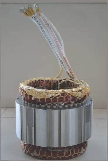
The motor frame holds the bearings that support the rotor, safeguards the coils, and allows the motor to be attached to the machine it will power. The stator core is permanently fastened into the motor frame.
The motor’s frame can take many forms, each tailored to the specific environment in which it will function. This can range from open-frame to completely submerged pump-motor installations.
Rotor
Squirrel Cage Rotor
Induction motors have a rotor made up of a spindle, bearings, a laminated iron core, and conductors. Rotor bars in lamination slots are more common than a winding because of the ease with which they can be manufactured.
Rotor bars are inserted into the rotor through holes pressed into the laminations. Short circuits are created at each end of the rotor bars by a solid conducting ring, which is typically a copper ring brazed or fusion welded to copper rotor bars.
Motors for smaller and medium-sized vehicles often use aluminum casting, with the added benefit of cast fins to facilitate airflow. The windings of a rotor, when exposed without the laminations, look like a metal cage, hence the common but incorrect name “squirrel cage” rotors. However, the standards refer to these machines simply as “cage” rotors.
Pictured in Figure 3 is a cast aluminum squirrel cage rotor with end fins. There are conductors in the rotor, but they are angled in relation to the rotor’s axis, as seen in the photograph. When the conductors are skewed, the power is transferred to the rotor more smoothly, resulting in reduced vibration and more consistent acceleration at start-up.
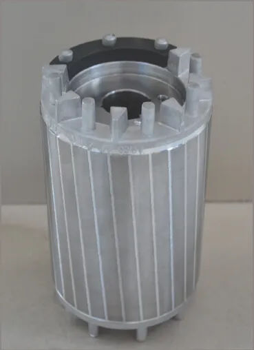
If you change the bars’ shape or size, you’ll see a difference in how well they work for motors. Increasing the inductance by further embedding the bars into the rotor reduces the starting current but increases the pull-out torque. Thus, centrifugal pumps and other loads that require low starting torques are ineligible for use with this rotor design.
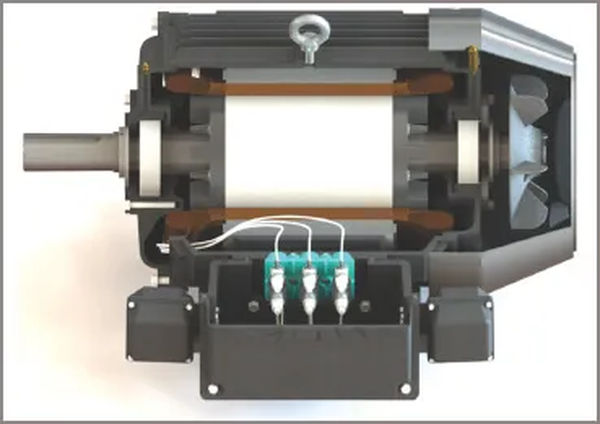
Figure 4 depicts a cross-sectional view of a full three-phase induction motor.
Wound Rotor
Insulated windings with the same number of poles and a configuration similar to the stator winding are installed on the rotor. The rotor’s three phases are connected in a star configuration, with the ‘Y’ point connecting them, and all three phases ending in slip rings at the same end of the rotor. (A typical wound rotor is shown in Figure 5.)
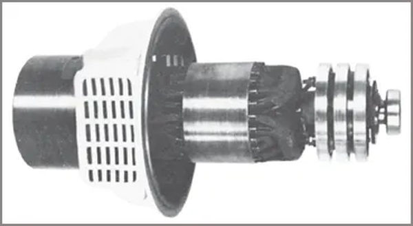
As shown in Figure 6 above, an external star-connected variable resistance is linked to the slip rings via brushes.

This rotor rheostat allows for the resistance of the rotor circuit to be increased during starting, resulting in increased starting torque with decreased starting current. When the rotor’s speed increases, the external resistance decreases, and the rotor’s reactance goes down.
By changing the resistance of the rotor circuit, the operating conditions allow for fine-grained regulation of the motor’s rotational velocity. As the resistance in a rheostat is increased, the speed and torque it can produce are diminished, and the efficiency of the system suffers from I2R losses.
Due to the higher production costs associated with the wound rotor, the wound rotor motor is more expensive than the squirrel cage motor. It has better starting characteristics than the squirrel cage motor and requires less starting current, but it has worse running characteristics and more frequent maintenance.
Motor Enclosures
A typical induction motor manufacturer has little say over the constraints of a given installation. As a result, we produce the motor in a wide variety of housings.
If the environment the motor is operating in is clean and dry, as it might be in a refrigerated display cabinet, then the motor enclosure may only need to provide a mounting for the bearings and a means for fixing the motor in a horizontal plane. The motor windings are protected from the elements and can cool off thanks to the enclosure’s open design.
Use the analogy of a water turbine pump for irrigation to illustrate the similarities and differences between the two systems. Vertical bore head mounting provides no cover for the motor and is the norm. The motor must be hermetically sealed so that no water can get inside, and it is cooled via convection.
A fan on the inside of the motor’s case moves the air around, dispersing the heat from the windings into the case. A second fan blows cool air across the exterior of the motor to dissipate the excess heat.
Terminal Block Arrangements
Squirrel Cage Motors
The three windings of a typical three-phase induction motor’s windings are typically brought out at both ends to a six-terminal block. Small, single-purpose motors, which can always be started online in either star or delta configuration, are the only other exception. There are only three terminals on these miniature three-phase motors (not including the earth terminal).
The phase ends are brought out to terminals in one of two configurations, determined by tradition and some attempts at standardization. Figure 7(a) depicts the standard setup, while Figure 7(b) shows an alternate network architecture.
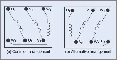
The goal is to create a standard set of connections for mechanics to use when installing the motor or re-wiring it after servicing. Motors can be wired in a star or delta configuration by connecting the winding ends together (see Figure 8).
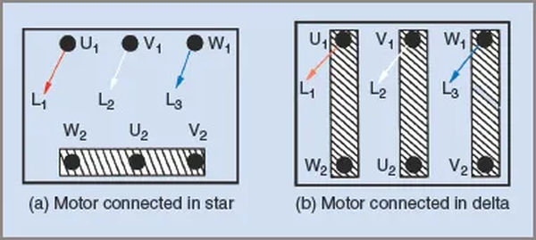
These are the key considerations:
| 1. | Each phase’s endings are separated from the other ends and not connected to any terminal pairs (see Figure 8). |
| 2. | When a motor is wired in a star configuration, the windings receive only 58% of the line voltage. |
| 3. | Each winding in a star configuration has its three ends connected by a single bridge. |
| 4. | The phase windings don’t have to have their beginnings and endings connected by a bridge, as shown. Both ends of the bridge are linked to the lines. |
| 5. | When connecting a motor in a delta configuration, you are limited to using the bridges. The voltage for each bridge is taken directly from the mains. |
| 6. | Figure 8 depicts bridges or shorting strips; however, these may need to be eliminated so that all six ends of the windings can be connected to a starter, such as a star-delta starter. |
Wound-Rotor Motors
It is common practice for wound-rotor motors to use either a star or delta configuration for the internal connection of the stator windings. Even though only three of the rotor windings’ ends are directly connected to the terminal block in a star configuration, the terminal block will still have six terminals because the other ends are brought out to the terminal block via slip rings.
They are typically distinguished from the line terminals of the stator windings by being physically separated from them or by employing a different type of terminal connector. It’s important to make sure the rotor terminals aren’t accidentally connected to the line voltage.