A capacitor is a type of electrical storage device. The capacity of the capacitor determines how much data can be stored. We’re going to look into the effects of adding a capacitor to a DC circuit consisting of resistors.
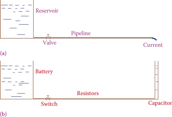
A capacitor is added to the basic DC circuit with a resistive load shown in Figure 1a to create the more complex circuit shown in Figure 1b. For greater concreteness, Figure 2 depicts an equivalent hydraulic circuit.
Adding a capacitor to a circuit is like putting a tall tank (with walls that are tall enough and comparable to the main reservoir) at the end of a pipeline.
As long as the reservoir (battery) is not depleted, water will continue to flow through the pipeline in Figure 2a, just as electricity will continue to flow through the circuit in Figure 1a.
As long as the smaller tank is not full, however, water flows as shown in Figure 2b. In other words, the pipeline current exists for a brief time before it abruptly ceases.
Furthermore, this water flow is not constant throughout the time frame. More water flows at the beginning (when the tank is empty), but the flow gradually decreases until it eventually reaches zero. Just like in a battery, this is what takes place in a capacitor-based electric circuit.


Current flows in a DC circuit with a capacitor inserted for a brief time after the switch is turned on. This current is stronger at first but gradually weakens. That’s when you know the capacitor is full and can no longer store any more electricity.
There is no current in the circuit now or in the future. Therefore, a capacitor in a DC circuit acts as a block and prevents any current from flowing, apart from a brief introductory period.
An electrical charge stored in a capacitor mimics the properties of live electricity. In the presence of high enough voltage, it can be harmful. If a capacitor is fully charged, its voltage will equal that of the battery (or other power source).
Disconnecting the capacitor from the circuit (turning off the switch) while it is charging causes it to charge only partially and to a lower voltage than the applied voltage.
A capacitor in a DC circuit blocks the current, except for only a short period following a change such as after a switch is closed (or opened if already closed).
The charging time of a capacitor is an intriguing quantity to learn. In fact, this time period is used for timing in a wide variety of devices, including electronic watches.
Capacitor charging/discharging time is directly proportional to water tank filling/emptying time (at a given water pressure) (based on the height of water and the resistance of the pipeline from which water discharges).
Capacitor Charging Time
A straightforward rule is provided for determining how long it will take to charge a capacitor. In Figure 1b, we can see a simple circuit made up of a resistor with resistance R and a capacitor with capacitance C, both of which are connected in series to a battery (power supply) with voltage V. We characterize a period of time as (the Greek letter corresponding to English t, and pronounced tow).
In a circuit with a capacitor or inductor and resistors, the time constant is the amount of time it takes for the value of the capacitor or inductor to change by 63%. (e.g., its power has been turned on or off).
τ = RC
When R is defined in ohms and C is defined in farads, is written as a fraction of a second. The time constant is shown to be sensitive to the parameters R and C. The capacitor takes about 5 times the time constant to charge to voltage V. The clock begins ticking as soon as the button is pressed. However, the capacitor won’t fully charge if the switch is opened before it’s done charging.
The time constant is sometimes shown by T (uppercase) instead of τ.
RC Circuit Time Constant Calculation
With a 12 V battery as the source of power, a series circuit is created by connecting a 51 Ω resistor and a 10 mF (milli-farad) capacitor. In what time does the capacitor fully charge?
Solution
First, we determine the time constant by using the formula:

Time needed to fully charge the capacitor = 5τ = (5)(0.51) = 2.55 seconds
A capacitor in a DC circuit acts as an open circuit and does not allow current to flow through it, with the exception of an extremely brief time at the beginning of the circuit. A capacitor’s charging or discharging time is roughly 5 the time constant.
Time Constant in DC Circuits
A capacitor can be used to store electricity for later use. As a component of a direct current (DC) circuit, it appears to be resistant to fluctuations in that voltage.
In electric circuits, a change in voltage is introduced when a switch is used to turn on or off the power supply. When a DC circuit with a capacitor is turned on, the capacitor is charged before the power is actually turned on. Similarly, when the power is turned off, a capacitor in the circuit first discharges its stored energy. Thus, there is a lag when activating a DC circuit and when deactivating it.
This lag means that when a voltage increase or decrease occurs, the capacitor-containing circuit does not immediately return to its original state; rather, it takes a while to reach equilibrium and settle into its final condition. Both the capacitor’s capacitance and the circuit’s resistance play a role in this lag.
The delay just mentioned is approximately 5× the time constant of the circuit.
A circuit with capacitors of equivalent capacitance C and resistors of equivalent resistance R has a time constant of
τ = RC
The time constant is calculated using seconds when the values of R and C are given in ohms and Farads, respectively.
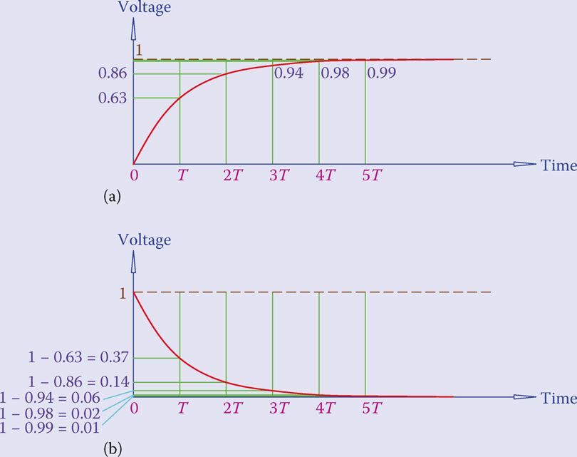
Down below, Figure 3 depicts the two scenarios where the voltage in a DC circuit is either increased or decreased. Therefore, the magnitude of this voltage change is normalized to 1, which corresponds to a hundred percent change.
- The voltage will change gradually over the time shown in the figure. T represents the time constant, and the percentage change after a given number of T units is also displayed.
- Part (a) of Figure 3 shows that after T seconds, the voltage has increased by 63% of the difference between the new and old values, when the voltage is increased (like turning on a switch).
- The figure depicts the previous value to be zero, but it may be anything other than zero. The voltage is increased to 86% of the new value after 2T sec. After 5T, nearly all of the eventual shift will have taken place.
- Lower voltage is shown in Figure 3(b). Sixty-three percent of the voltage drop occurs after one time constant if the change is caused by turning off the power, leading to a final voltage of zero. In other words, there is a 37% decrease in voltage in the circuit.
- After 2T, the voltage drops to 14%, and after 5T, it drops to 99%, resulting in 1% of the original magnitude of the voltage in the circuit. After that point, there is essentially no voltage shift.

Capacitors find widespread use due to the delay they introduce, particularly in electrical applications requiring control and regulation and in electronic circuits used in radio, television, communications, and similar fields.
By changing the time constant, through R and C, the desired delay can be obtained for any application.