The three fundamental electric quantities (voltage, current, and resistance) can be measured by any multimeter, but more advanced models often include additional measuring capabilities. Analog and digital multimeters are the two primary options available.
When dealing with electrical and electronic components, a multimeter is an indispensable tool. Values must be checked, and voltage, current, and resistance measurements must be taken in a circuit in order to diagnose problems or determine which part of the circuit is broken.
Analog Multimeter
Needle movement away from the zero point is the primary input for an analog multimeter’s calculations. Just under the needle is where you want to read your measurement’s correct value.
The galvanometer, which is essentially a tiny winding, is the heart of any analog meter. The winding is mounted on a pin with a needle that can spin around the pin. The needle can be manually reset or a spring can be used to return it to its initial zero setting. It strays from its equilibrium position in response to the strength of the current passing through the winding. This means that a galvanometer is extremely sensitive to electrical current.
A galvanometer can be modified to serve as an ammeter, voltmeter, or ohmmeter by simply adding the appropriate components. In an analog meter, the needle always swings from left to right.
- Galvanometer: A device in which an electric current flows through a coil, causing a needle attached to the coil to spin around a pin shaft. The needle’s range of motion is constrained by the coil, which also functions as a spring. Although a galvanometer is typically used to measure current, it can also be used to measure other electric quantities by changing the position of the needle.
- Ohmmeter: Instrument for gauging electrical resistance.
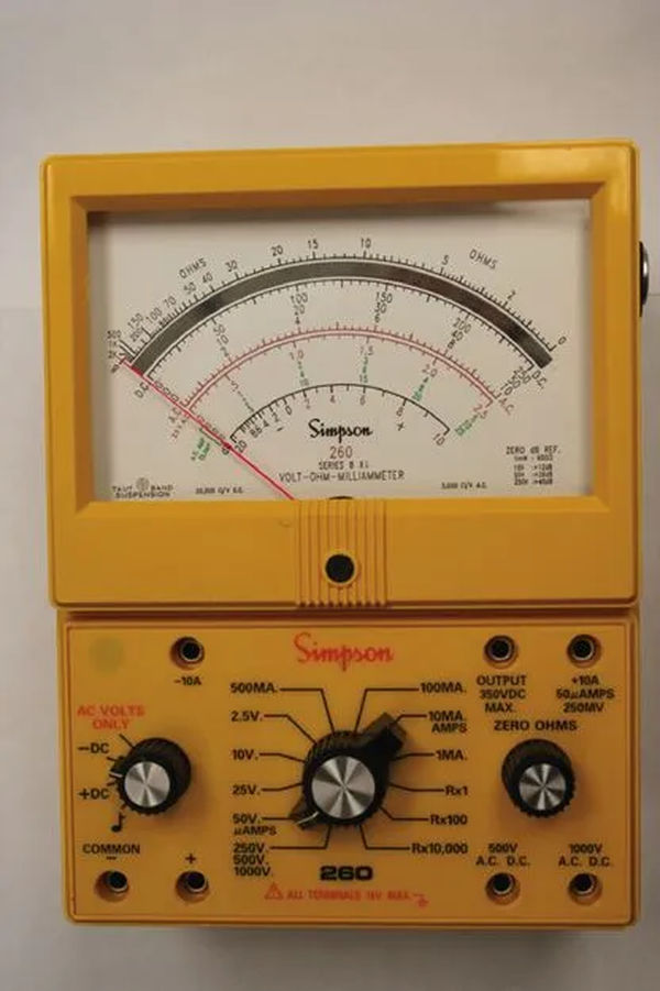
The analog multimeter shown in Figure 1 is fairly typical. A rotary switch allows the user to choose between different measurement categories and ranges.
Some meters have fewer terminals than others, and not all meters have the same range of values or the same number of terminals. Figure 2 depicts more switch and terminal details from the multimeter shown in Figure 1.
Switches for AC, -DC, and +DC complement the primary selector for switching between volt and ohm or amp and selecting a range of values (such as 100 mA, 500 mA, 25 V, and 500 V).
Black (common) and red (signal) leads connect to the two primary terminals, while 10 A current (current greater than 500 mA and up to 10 A), 500 V, and 1000 V connect to separate terminals (higher voltages).
The black lead still connects to the common terminal, but the red lead must be inserted into the right port in order to take readings of these relatively high values.

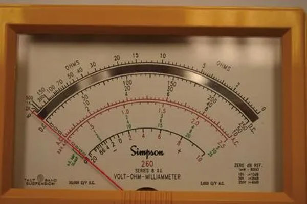
The range of values measured by the multimeter in Figure 1 are depicted in Figure 3. It’s clear that the graduations are unique, and that different numbers correspond to different needle positions.
There is at least one selector switch position for every graduation. For a selector switch’s range of 2.5, 25 and 250 (see Figure 2), for example, the graduations ending in those numbers are used, while for other selections, the numbers are between 0 and 10. (which must be multiplied by a power of 10, accordingly).
As an additional note, the AC values in the displayed meter are shown in red, while the DC values are shown in black.
Keep in mind that the ohm’s zero value (the top scale) is located far to the right (all the other zero values are on the extreme left). This is due to Ohm’s law, which states that the ratio of voltage to current decreases as resistance increases, and vice versa.
A Digital Multimeter
Figure 4 is a representation of a common digital multimeter (DMM). The rubber housing helps to absorb impact and prevents scratches. A digital multimeter is typically more convenient to use because it instantly displays numerical readings.
The digital multimeter (DMM) is a non-contact measuring device that works by converting an analog signal to a digital value.
A digital multimeter (DMM) is an electronic instrument for measuring electrical quantities such as resistance, current, and voltage, as opposed to an analog multimeter (OM) in which the position of a rotating needle indicates the quantity being measured.
A digital multimeter (DMM) is similar to an analog multimeter in that it has a common terminal to which the black lead is connected and the red lead is inserted into one of the other terminals.
The red terminal goes into the hole to the right of the common (com) terminal in the digital multimeter depicted in Figures 4 and 5, but the other two holes are used for measuring current (based on its value if in the order of amps or much smaller).
The left terminal, which can handle a greater current, should be used before the center terminal, which offers greater precision. Doing so prevents the delicate meter from being exposed to a current that is too high for it to handle (or blow its fuse).
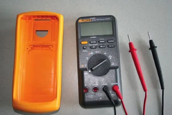
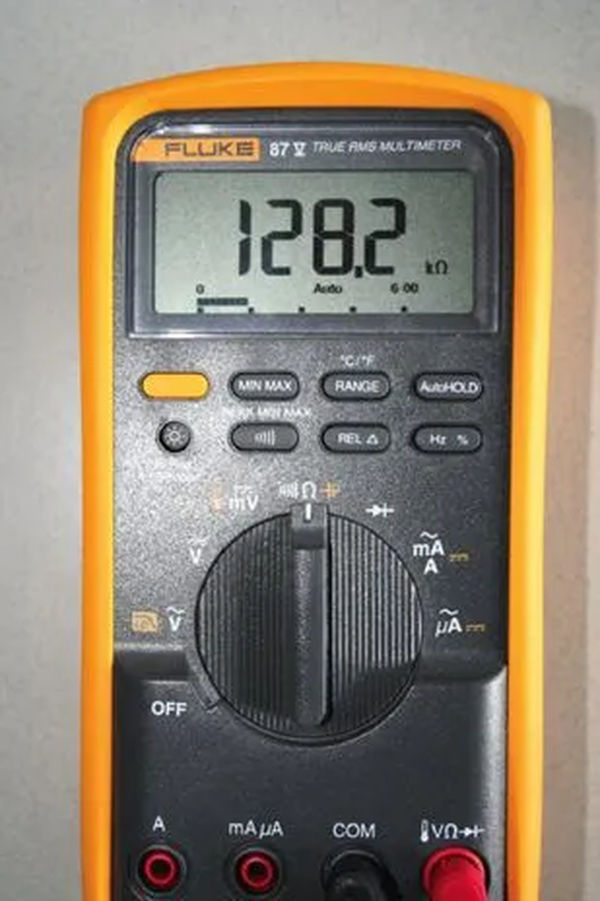
The switch on the multimeter depicted in Figure 4 can be set to off, AC voltage, DC voltage, small DC voltage (mV), resistance (ohm, Ω), and current (Ampere A, milliamp mA, and μA micro-amp).. The diode comes in a few more varieties (test).
Fig. 5 depicts a better digital multimeter with four digits. Some less expensive DMMs only go up to three digits. Typically, the scale is automatically adjusted based on the measured values; for example, the scale in Figure 5 is set to k. (appearing on the screen).
Measuring Resistance using Digital Multimeter
An ohmmeter or multimeter can be used to determine a resistor’s or a circuit component’s resistance. A multimeter’s ohmmeter function, or a standalone ohmmeter, measures the amount of current flowing through a circuit in which the object being tested is the primary load.
However, the levels are graduated based on resistance rather than current. There are several key distinctions between an ohmmeter and a voltmeter or ammeter in this regard:
- Current and voltage meters do not require batteries because they are already powered by the electrical current being measured, but an ohmmeter does (when the switch is closed).
- Ohm’s law states that larger current flows through circuits with lower resistance, and smaller current flows through circuits with higher resistance. For this reason, the highest current will be at the far right of an analog meter’s scale, where the zero resistance reading will be located.
- Because the power of the ohmmeter’s battery decreases over time, the instrument’s needle must be periodically reset to zero using the zero adjustment knob. Before taking any readings with an analog ohmmeter, it is always necessary to readjust the zero. Connect the two leads’ terminals together and set the zero point by turning the knob.
- Always disconnect the power to the circuit whose resistance is being measured before taking a reading. If you don’t do that, the reading will be off.
A resistor or other resistive element’s value can be checked and measured with an ohmmeter. It can also be used to test for a short (when two points make unneeded contact) or to determine whether or not a circuit is open.
The power to the circuit must be turned off before the resistance of the component can be measured.
Checking a Capacitor and an Inductor with an Ohmmeter
Capacitors can also be tested for quality using an ohmmeter (typically only analog meters). A capacitor can become shorted (when the capacitor’s two plates touch) or open if it is tampered with (contacts are lost).
A capacitor is measured with an ohmmeter to ensure it is functioning properly. If it’s short, the meter needle won’t budge because of the high current (almost no resistance).
Once open, it reveals extremely high resistance (the needle stays in the very left side of the meter). The meter’s needle should shoot to the right and then slowly head back left if the capacitor is functioning properly.
Similar to how an ohmmeter can be used to test a resistor’s health, an inductor can be tested for damage in the same way. You can use either a digital or an analog multimeter.
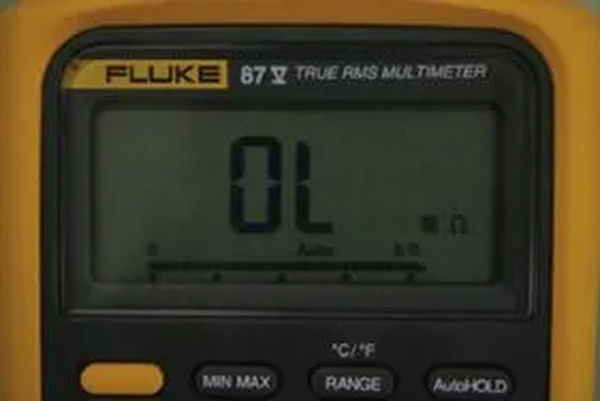
Figure 6 shows the overload symbol represented by the letters “OL” that appears on the screen of a digital multimeter when the value to be measured exceeds the range of values selected.
In particular, if the meter reads “OL” while measuring resistance, the circuit is open, which corresponds to a very high resistance reading.
Inductors can be either open or shorted. Connecting its two ends to an ohmmeter should reveal whether it is open or closed. The resistance of a short inductor is infinitely small. An ideal inductor has a small resistance value, but not zero.
