A filter is a circuit in a power supply section that smooths the pulsating DC to make it more consistent. A filter minimizes or removes ripple voltage from a rectified output by opposing changes in voltage and current.
By connecting parallel capacitors and series resistors or inductors to the rectifier’s output, filtering can be achieved. Both capacitors and inductors can be used to smooth voltage and current, respectively.
DC Power Supply Filter Types
1. Capacitive Filters
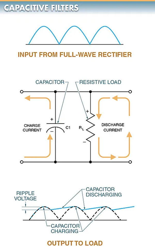
A capacitor and a resistor connected in parallel make up a capacitive filter. To a load, the capacitive filter delivers its maximum voltage output.
Due to the necessity of a large capacitor, electrolytic capacitors are the standard. Capacitor C1 is charged to its maximum potential as DC voltage from a rectifier is pulsed across it. Refer to Figure 1.

The capacitor gradually discharges through the resistive load RL between peaks, reducing the voltage.
Ripple voltage is the amount of varying voltage present in a DC power supply.
The ripple voltage is the drop in voltage across a capacitive filter before the capacitor starts charging again. Between voltage peaks, a capacitor discharges an amount determined by the load resistance and the capacitor’s resistor-capacitor (RC) time constant.
Smooth output can be achieved with large load resistance and capacitance thanks to the reduced ripple voltage. The capacitive filter’s ripple voltage grows as its load does.
2. L-section Resistive Filters
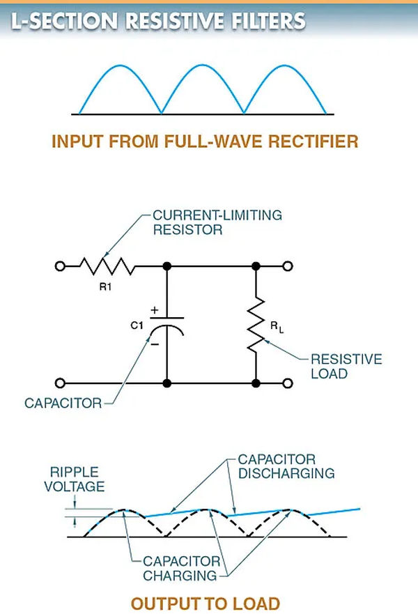
By using a resistor and capacitor as an RC time constant, an L-section resistive filter can drastically reduce or even eliminate DC ripple at the circuit’s output.
Surge currents can be mitigated with the help of a current-limiting resistor and an L-shaped resistive filter (R1). Observe the second figure.
In order to reduce surge currents, R1 restricts current flow to a capacitor. When connecting the filter’s rectifier and input capacitor, R1 must always be used in series with both components. As a result, the rectifier is shielded from the large charging current that flows through it from input capacitor C1 at the beginning of the circuit’s activation.
A resistor with a low value, typically 50 or less, is used in this context. The resistor’s filtering is inferior to that of competing filters, but it’s cheaper.

3. L-section Inductive Filters
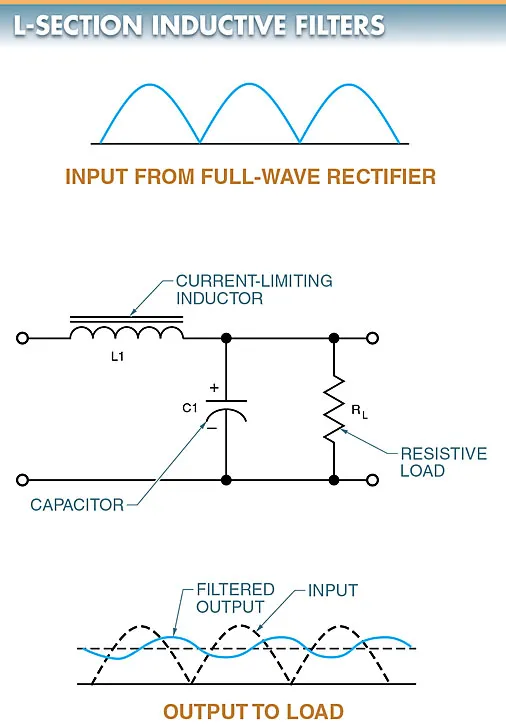
Using a current-limiting inductor and a capacitor, an L-section inductive filter is able to mitigate surge currents. A look at Figure 3 is in order.
In order to resist a change in current, a series-connected inductor (L1) generates a counter electromotive force (CEMF) or counter voltage. Because of this, the capacitor charges slowly and can withstand much less of a surge.
Since the CEMF of the inductor tends to cancel out the effects of the ripple voltage, it also helps the filtering effect of the capacitor.

The inductive reactance in the circuit also demonstrates the operation of the L-section inductive filter.
High inductive reactance is created by the pulsating DC voltage as it is applied to the inductor. As a result, the inductor tends to prevent the alternating DC voltage from passing through. The inductor will allow the direct current (DC) portion of the signal to pass through. The capacitor will allow through any pulses that the inductor does not stop.
4. Pi-Section Filters
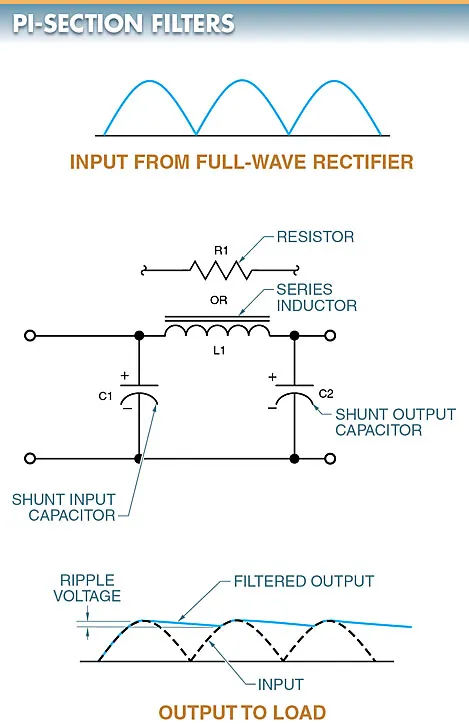
In order to remove the AC ripple from a rectified waveform, a pi-section filter is used. This filter is constructed using two capacitors and an inductor or resistor.
The Greek letter pi () is where the name “pi-section filter” originates from, as the filter’s configuration looks like the symbol for pi. Pi-section filters can be either inductive or resistive.
In general, there are three parts to a pi-section filter. C1 is the shunt input capacitor, L1 is the series inductor (choke), and C2 is the shunt output capacitor in a pi-section inductive filter. Notice in particular Figure 4.
Most of the AC ripple current is grounded as the input voltage reaches the first capacitor (C1). As a result, L1 receives a much more uniform current. This is because L1 has a much higher inductive reactance to the remaining AC ripple than a resistor in a resistive pi-section filter would, and so it effectively blocks the AC ripple. When all else fails, C2 shunts the residual ac ripple to ground. It produces a DC voltage that is relatively smooth.

To generate pure DC voltage, full-wave rectifiers are typically employed. Although the filtering process greatly reduces the amount of ripple present in the DC voltage that is delivered, some ripple may still be present.
The ripple in a 12 VDC power supply that operates between 11.8 V and 12.2 V is 0.4 V. The less rated ripple there is in the power supply, the better.