Hysteresis Loop, also known as Magnetization Curve, is a curve or loop plotted on B-H coordinates that displays the variation in magnetization of a ferromagnetic material when subjected to a periodically reversing magnetic field.
Non-Magnetic Materials
It has been found that the density of flux has no effect on the reluctance of non-magnetic materials. The magnetic flux () and flux density (B) are proportional to the magnetic field strength (H) and the magnetic moment (IN), respectively.
The graph of B versus H for non-magnetic materials will be a straight line because B varies directly with H.
Magnetic Materials
A curve can be seen when the B values are plotted against the H values for a magnetic material. The data for the iron sample are shown in Table 1.
Table 1 Magnetization Curve for a Magnetic Material
| Magnetizing force H (At/m) | Flux density B (Wb/m2) | Permeability μ= B/H | Relative permeability μr = μ/μo |
| 100 | 0.04 | 0.00040 | 318 |
| 200 | 0.12 | 0.00060 | 477 |
| 300 | 0.40 | 0.00130 | 1058 |
| 400 | 0.90 | 0.00225 | 1790 |
| 500 | 1.00 | 0.00225 | 1591 |
| 600 | 1.06 | 0.0017 | 1408 |
| 700 | 1.11 | 0.00159 | 1265 |
| 800 | 1.15 | 0.00144 | 1146 |
| 900 | 1.18 | 0.00131 | 1042 |
| 1000 | 1.21 | 0.00121 | 963 |
| 1200 | 1.25 | 0.00104 | 828 |
| 1400 | 1.29 | 0.00092 | 732 |
| 1600 | 1.32 | 0.00083 | 660 |
| 2000 | 1.36 | 0.00068 | 541 |
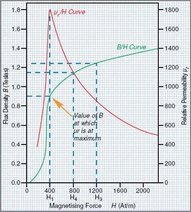
Figure 1 depicts a graph drawn from these data. Since B values are plotted against H values, the graph is called a B/H curve or magnetization curve. These curves are frequently employed in the evaluation of magnetic properties of various materials.

Magnetic Saturation
When the magnetizing force (H) is low, a small increase in H results in a large increase in the flux density (B), as shown in the B/H curve in Figure 1. (B). The steeply sloping part of the curve illustrates this point.
It can be seen that as both H and B grow larger, the effect of H on B becomes smaller and smaller. As H is increased to its maximum value, H3, only a marginal increase (from B2 to B3) is produced. The flux density decreases as magnetization approaches 2000 A T/ m. Saturation of the magnetic field is evidenced by this.
At a flux density close to the middle of the ‘knee’ of the B/H curve, it is said that saturation occurs. Magnetizing steel past its magnetic saturation point is impractical from a cost perspective. There is no point in increasing the magnetizing current if it only increases the flux density by a small amount because that is a waste of electrical power.
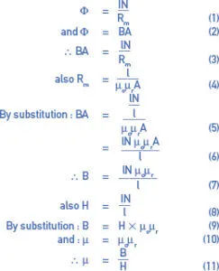
Different flux densities have different effects on the permeability of ferromagnetic materials. By solving the basic magnetic equation, we can show that for a given flux density, permeability (μ) is equal to the ratio B/H.

Iron typical B and H values can be found in Table 1. Permeability can be determined for any given flux density and magnetizing force in this way. Table 1 columns 3 and 4 show the calculated values for and r based on the given values for B and H.
Figure 1 shows the r/H curve calculated by plotting r values against H values. According to the graph, the permeability curve sharply increases to a peak. At this maximum permeability point, the curve drops off sharply. The permeability decreases as H is increased past the point of magnetic saturation.
Comparison of B/H Magnetization Curves
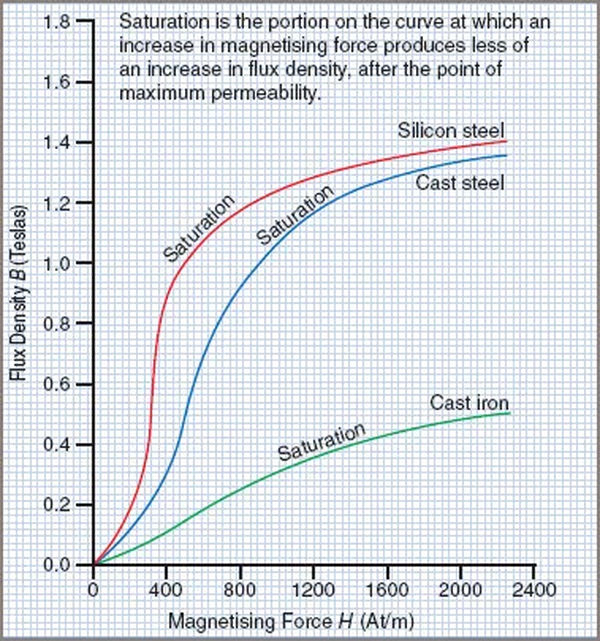
Magnetic susceptibility curves for silicon steel, cast steel, and cast iron are shown in Figure 2.

The following should be taken into consideration:
- The magnetic saturation of the materials typically occurs in the region corresponding to the centers of the knees of the respective curves.
- The flux density produced by silicon steel is significantly higher than that of cast steel or cast iron at low H values.
- The flux density at which silicon steel saturates is lower than that at which cast steel saturates.
- Saturation occurs in cast iron at flux densities that are much lower than those required by silicon steel or cast steel. Furthermore, it is much more challenging to magnetize than the previously mentioned materials.