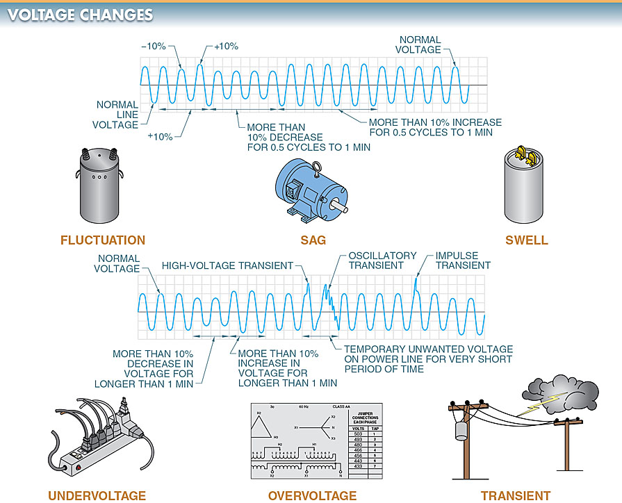
In order to power a load via a rotating shaft, AC motors generate work. The amount of work accomplished is proportional to the shaft’s speed and the torque applied to it by the motor. All motor drives serve the overarching purpose of regulating the rotational velocity and torsional force of a motor.
An important part of a variable frequency drive’s job is to keep an eye on the drive’s temperature, the motor’s current, the drive’s voltage, and any other relevant operating parameters to ensure the motor is being controlled safely. When an issue arises, power is automatically cut to the motor by the drive. In some cases, it is possible to monitor and show errors and other status information from the drive.
A variable frequency drive’s primary purpose is to regulate the rotational speed and torque of an electric motor, but it can have a variety of specialized features that are either built in, programmed, or sent to the drive via on-board communication with a personal computer or programmable logic controller.
The speed of an AC motor can be adjusted by adjusting the frequency (in hertz). A motor’s operating frequency can be adjusted with a variable frequency drive from zero to several hundred Hertz.
To prevent motor and driven load damage, variable frequency drives have preset minimum and maximum operating speeds. When a motor is operated at a speed higher than its nameplate maximum, it suffers damage. It is not recommended to exceed 2% of the nameplate speed when operating an AC motor.
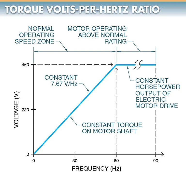
Volts per Hertz (V/Hz) is the relationship between voltage and frequency that exists in a motor and is expressed as a ratio. Controlling the V/Hz ratio applied to an AC motor controls motor torque.
A constant V/Hz ratio allows an AC motor to produce its rated torque. Due to the voltage increase occurring at the same rate as the frequency, the torque delivered by the motor shaft remains constant during acceleration (at any speed between 1 Hz and 60 Hz). At the point where a variable frequency drive is delivering full motor voltage, increasing the frequency does not increase torque on the motor shaft because the voltage cannot be increased further to maintain the V/Hz ratio. For an example, see Fig. 1.
Carrier Frequencies
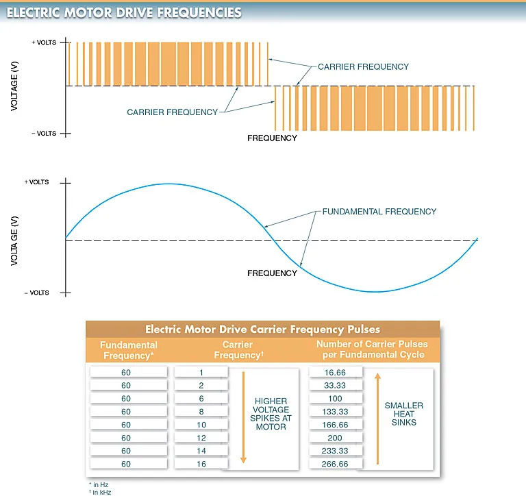
The carrier frequency is the frequency that controls the number of times solid-state switches in the inverter of a motor drive with pulse width modulation turn on and off.
The more discrete pulses used to reproduce the fundamental frequency, the higher the carrier frequency.
The fundamental frequency is the frequency of the voltage used to control motor speed.
By plugging the relevant numbers into the following formula, we can calculate the carrier frequency pulse count for each fundamental frequency.
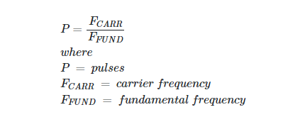
The voltage used by a motor is called its “fundamental frequency,” but it is the “carrier frequency” that actually supplies that voltage to the motor.
Motor drives typically have a carrier frequency between 1 kHz and 16 kHz. If a carrier frequency of 6 kHz is used to generate a fundamental frequency of 60 Hz, then there will be 20 discrete pulses in each 60 Hz cycle. The example is in Figure 2. Higher carrier frequencies produce sine waves that more closely resemble those at the fundamental frequency.
An example of an application where motor noise is a problem is in an HVAC system, which can be heard throughout an entire building. Raising a motor’s frequency above the standard 60 Hz causes it to make more noise. Due to the motor’s amplification, audible noise in the 1 kHz to 2 kHz range is present.
When compared with a motor running off of a pure 60 Hz sine wave supplied by a magnetic motor starter, one that is connected to a Variable frequency drive that provides a carrier frequency of 2 kHz is roughly three times noisier.
In order to reduce background noise, manufacturers have increased the carrier frequency to levels inaudible to humans. In a variable frequency drive, the solid-state switches in the inverter experience increased power loss (thermal loss) at high carrier frequencies.
To compensate for the increased thermal loss, variable frequency drives should either have their ratings lowered slightly or their heat sinks made larger. When a motor drive is derated, its maximum allowable power output drops. Drive prices go up as heat sink sizes grow larger. View Figure 3.
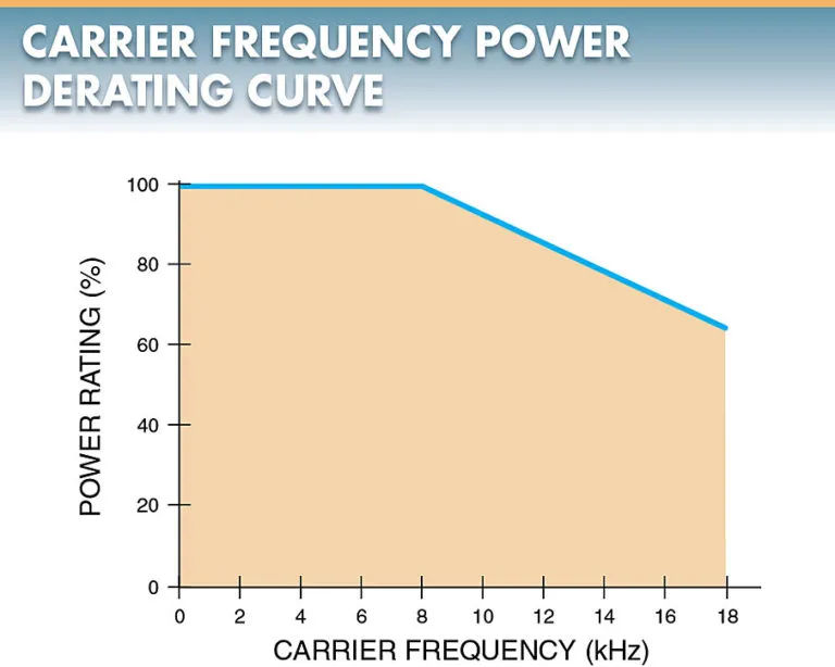
As a general rule, higher carrier frequencies are preferable to lower ones. An increase from 1 kHz to 3 kHz in carrier frequency, for instance, does not have the same effect on motor temperature as an increase from 6 kHz to 8 kHz because the former more closely mimics a pure sine wave. Less heat is generated as a result of the voltage being delivered to the motor more closely approximating a pure sine wave. Keeping the motor at a slightly cooler temperature extends the life of the insulation.
Pulse Width Modulation
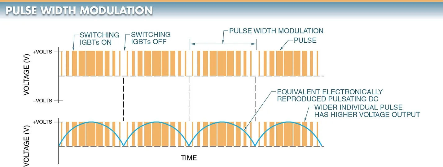
Pulse width modulation (PWM) is a method of controlling the amount of voltage sent to a motor by converting the DC voltage into fixed values of individual DC pulses.
In order to regulate a motor’s rotational velocity and torsional stiffness, variable frequency drives must regulate the voltage supplied to the motor.
The output voltage is modulated by pulse width modulation. Transistors, typically insulated-gate bipolar transistors (IGBTs), are switched on and off rapidly to generate the fixed-value pulses. The voltage can be adjusted by changing the pulse width (time ON) and/or the frequency. The DC voltage output will be greater if the pulse widths are larger. Look at Figure 4. To generate AC sine waves, pulse width modulation (PWM) of DC voltage is also utilized.
PWM with AC voltage requires two IGBTs per phase. A sine wave is created by using one IGBT to generate positive pulses and another IGBT to generate negative pulses. Six IGBTs (two per phase) are used to mimic three-phase power because AC drives are typically used to control three-phase motors. View Figure 5.
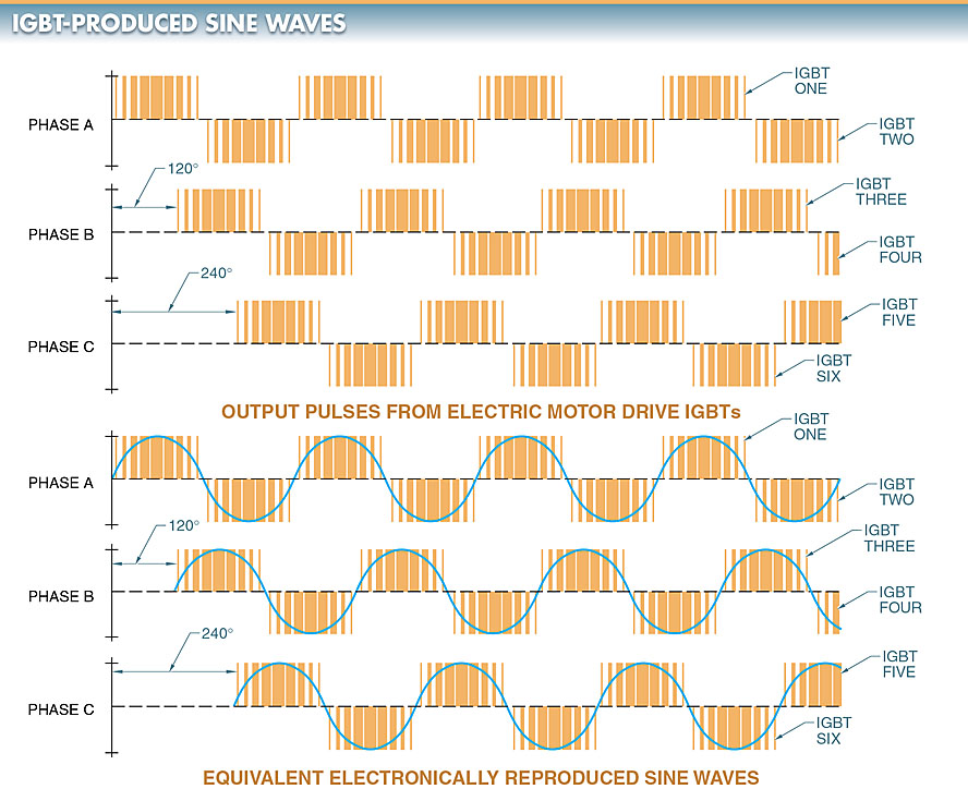
When simulating alternating current (AC) sine waves, higher IGBT switching frequencies are preferable to lower ones. Lower temperatures are produced by motors as the accuracy of the simulated AC sine waves increases.
