This article serves as a hardware design reference, primarily introducing the USB C cable wiring diagram, the pin definition of the 24Pin USB Type C interface, and the proper way to connect the core wires.
First, it’s important to define “24Pin USB C” and its “pins.”


In this article, we focus on the male end of the USB C cable.
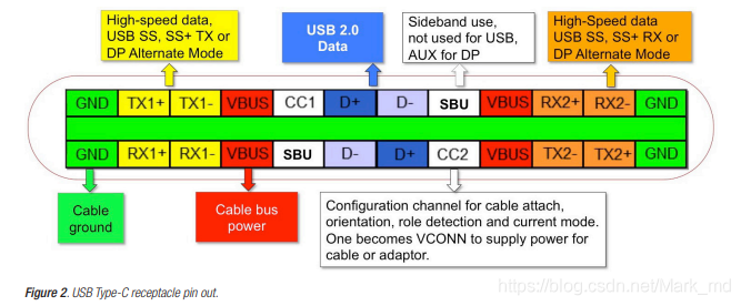
The Pin position of the same function is seen to be diagonally symmetrical with respect to the center point. The pin function of the male connector fits snugly into the female connector after being inserted in either direction.
Moreover, both VBUS and GND have 4 Pins and can deliver power independently. As a result of these improvements, USB-C can supply a much higher maximum current (5A) than its predecessors with the same connector.
Pins function definition
| PIN | Name | Functional description | PIN | Name | Functional description |
| A1 | GND | Ground/Drain Wire | B12 | GND | Ground/Drain Wire |
| A2 | SSTXp1 | SuperSpeed differential signal #1, TX, positive | B11 | SSRXp1 | SuperSpeed differential signal #1, RX, positive |
| A3 | SSTXn1 | SuperSpeed differential signal #1, TX, negative | B10 | SSRXn1 | SuperSpeed differential signal #1, RX, negative |
| A4 | VBUS | Power Supply | B9 | VBUS | Power supply |
| A5 | CC1 | Configuration channel | B8 | SBU2 | Sideband use (SBU) |
| A6 | Dp1 | USB 2.0 differential signal, position 1, positive | B7 | Dn2 | USB 2.0 differential signal, position 2, negative |
| A7 | Dn1 | USB 2.0 differential signal, position 1, negative | B6 | Dp2 | USB 2.0 differential signal, position 2, positive |
| A8 | SBU1 | Sideband use (SBU) | B5 | CC2 | Configuration channel |
| A9 | VBUS | Power Supply | B4 | VBUS | Power Supply |
| A10 | SSRXn2 | SuperSpeed differential signal #2, RX, negative | B3 | SSTXn2 | SuperSpeed differential signal #2, TX, negative |
| A11 | SSRXp2 | SuperSpeed differential signal #2, RX, positive | B2 | SSTXp2 | SuperSpeed differential signal #2, TX, positive |
| A12 | GND | Ground/Drain Wire | B1 | GND | Ground/Drain Wire |

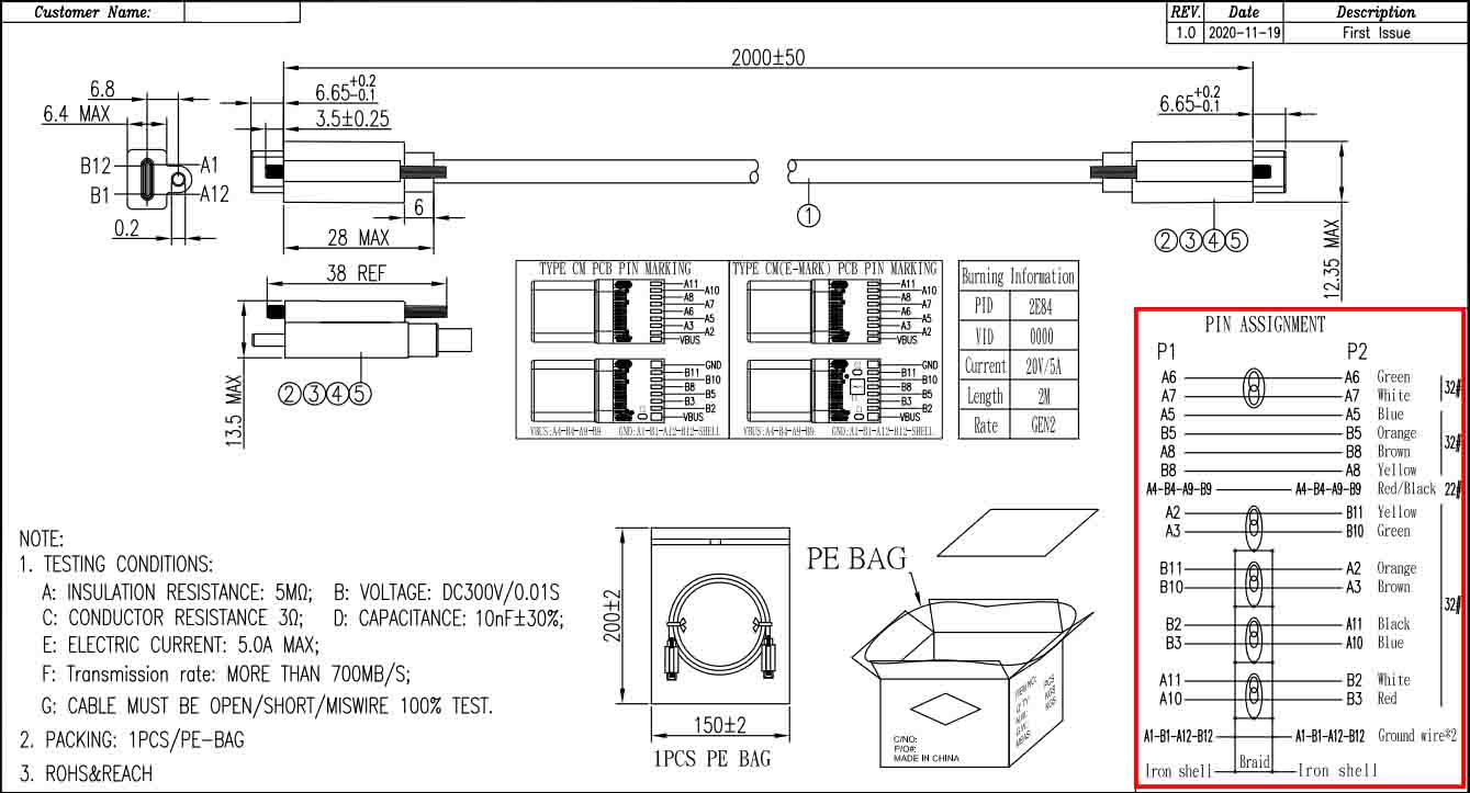
USB C cable wiring diagram
Here is a diagram showing how to wire a USB Type-C cable: (male to male, only for reference)

Why do 24Pins USB connector use 16 core wires?
There are 24 pins on a 24PIN USB C connector, but only 16 cores in a fully functional USB C cable. Since all four VBUS pins and all four GND pins are connected to the same VBUS solder joint on the PCB board, and since 8 becomes 2, reducing 6 solder joints, and since B6 and B7 do not exist, the total number of solder joints is only 16, which is equivalent to a 16-core wires (24-6-2=16).
How does USB C PCB board actually weld the core wires?
USB C MALE’s printed circuit board (PCB) comes in a wide variety of styles. In reality, each Pin’s location on the PCB does not correlate to its physical location on the interface.
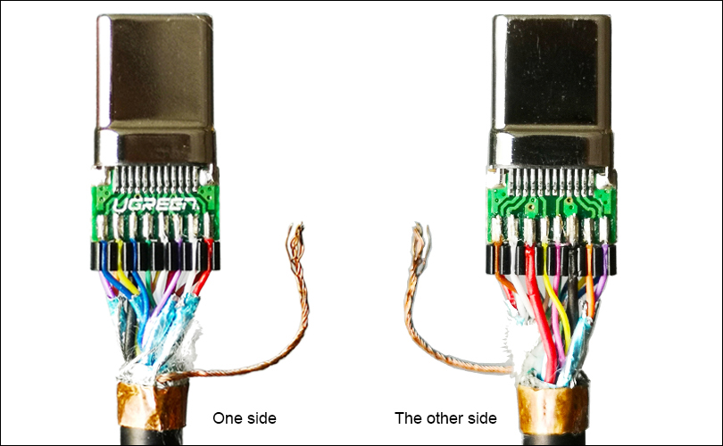
Most commonly, one will use a combination of red and black wires for the power supply (VBUS), and one will use braiding as GND, soldering it to the GEN terminal or the inner shielded metal shell, as shown below.

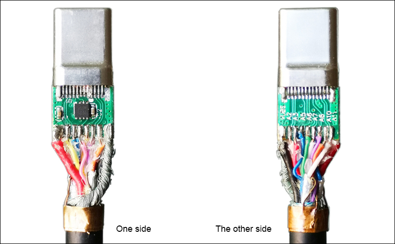
For example, the original VBUS location is insufficient for cables that demand high current (say, 5A) due to the thickness of the power supply wires. To weld the bulky power wires, the VBUS terminal of the PCB board must be moved to both sides of the board, as shown in the figure below.

When you need a custom USB cable made, come to P-SHINE, as we are the Intel and Western Digital supplier as well as the original design manufacturer for many popular brands like C2G, Ugreen, Anker, etc.