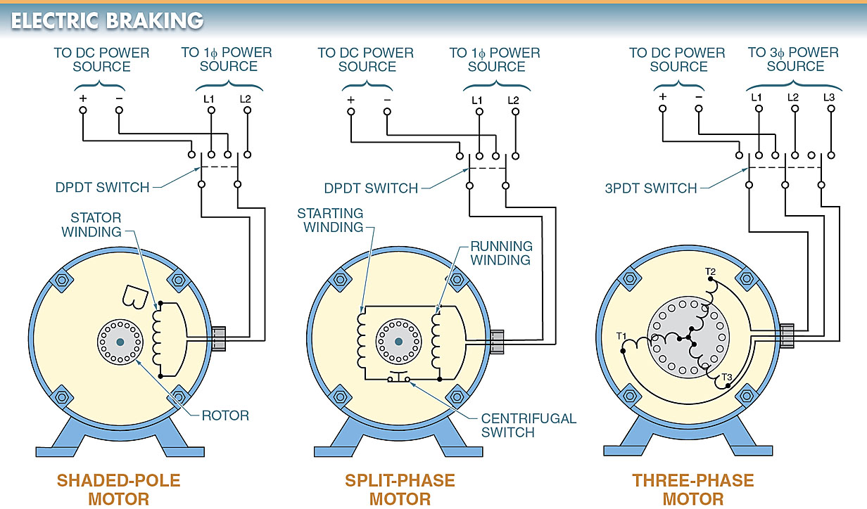
When the AC power to an electric motor is cut off, the motor can be braked using electric braking by applying a direct current (DC) voltage to the motor’s stationary windings. DC injection braking is another name for electric braking. Look at the example in Figure 1.
Most AC motors can be stopped with ease using electric braking. The braking action of electric brakes is instant and smooth, even when applied to high-speed or high-inertia loads.
Electric Braking Operating Principle
The shaft of an electric motor turns because of the principle that states that unlike magnetic poles attract each other and like magnetic poles repel each other. The creation of the magnetic fields, however, varies from motor to motor.
In AC induction motors, the transformer action induces the opposite magnetic fields from the stator windings into the rotor windings. As long as the AC power is on, the motor will keep turning.
When the AC voltage is cut off, the motor gradually stops turning because there is no longer an induced field to keep the shaft turning.
If the time spent coasting is unacceptable, especially in an emergency, electric braking can be used to bring the vehicle to a quick stop.
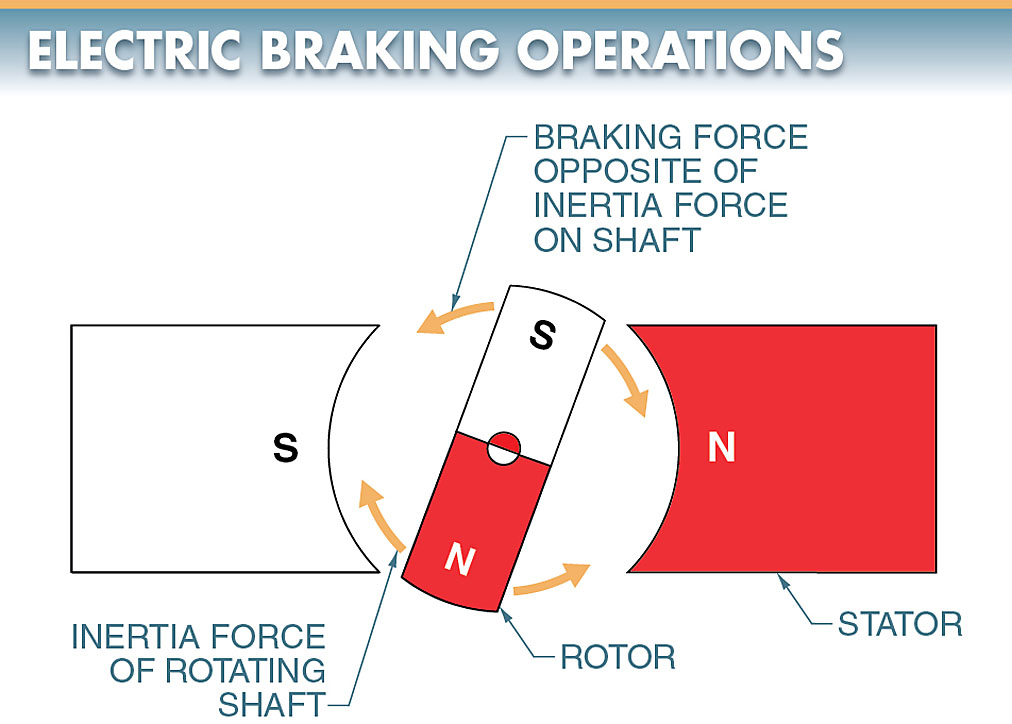
Electric braking is accomplished by applying a DC voltage to the stationary windings once the AC voltage is removed. The DC voltage creates a magnetic field in the stator that does not change polarity.
A magnetic field is produced in the rotor by the stator’s permanent magnetic field. When the rotor and stator’s magnetic fields are in phase, the stator’s magnetic field, which does not reverse polarity, tries to halt the rotor (N to S and S to N). For more information, please refer to Figure 2.
The rotational inertia of the load on the motor shaft is the only force capable of preventing the rotor from stopping upon initial alignment. However, the electric motor stops quickly and smoothly because the stator’s braking action is always in play.
DC Electric Braking Circuit
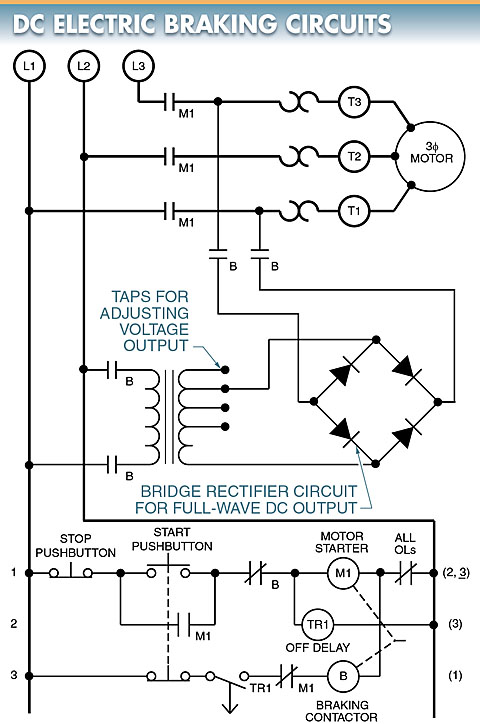
If you want to quickly stop an electric motor, you can do so by applying DC power after the AC has been turned off. View Figure 3. The AC is rectified into DC using a bridge rectifier circuit, as is common in DC braking circuits. A magnetic motor starter is used in this circuit to connect a three-phase alternating current motor to three-phase power.
An ordinary stop/start pushbutton station with memory operates the magnetic motor starter. The magnetic motor starter has a timer attached in parallel with it to prevent accidental startup. Pushing the stop button initiates a short delay in the off-delay timer’s control of a NO contact, which supplies power to the braking contactor. The motor will not stop until the timing contact is set to remain closed.
Braking Contactor
Two motor leads are connected to the DC supply via the braking contactor. The amount of braking torque applied to the motor can be modified using a transformer with tapped windings.
The same effect could be achieved with current-limiting resistors. This affords the option of a light or heavy hand when it comes to stopping power. The magnitude of the stopping force increases with increasing DC voltage.
Interlock System in Electric Motor
The electric motor starter and the braking contactor cannot be energized simultaneously because of an interlock system in the control circuit. This is necessary because the motor should never have both the AC and DC power supplies connected at once.
Electrical braking circuits must always employ full interlocking. Mechanical, electrical, and pushbutton interlocks are all part of a system that uses total interlocking. This circuit, like most electric braking circuits, can be operated with a regular forward/reverse motor starter.
Dynamic Braking in DC Motors
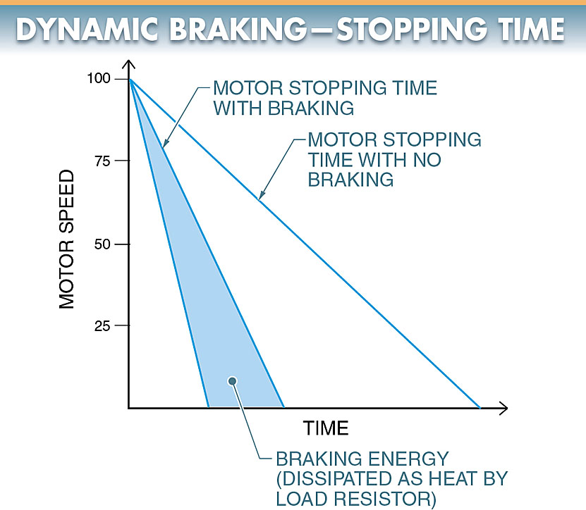
Dynamic braking is a method of an electric motor braking in which a motor is reconnected to act as a generator immediately after it is turned off.
With these wires connected, the motor behaves like a loaded generator, producing a retarding torque that immediately shuts it down.
Through a process known as “generator action,” the mechanical energy of rotation is transformed into electrical energy, which is then lost as heat in a high-power resistor. To see this, please refer to Figure 4.
DC motors are the most common candidates for dynamic braking because the brushes allow for direct access to the armature, allowing for the generation action to be utilized. The brushes in DC motors provide the necessary entry point. Please refer to Figure 5.
Since DC motors are frequently used to lift and move heavy loads that can be difficult to stop, dynamic braking of a DC motor may be required.
The DC motor’s armature terminals are temporarily severed from the circuit’s power source and connected across a resistor to simulate a load. As the energy in the motor is quickly dissipated, the motor stops spinning rapidly as the resistor’s resistance decreases.
The DC motor’s field windings are still wired to the power source. An electromotive force opposing that of the motor is produced by the armature (CEMF). An electric current flows through the armature and the resistor due to the magnetic field.
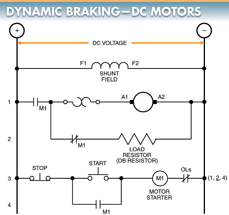
The electrical watts are lost as heat in the resistor as a result of the current. This drains power and reduces the speed at which the motor spins.
As the motor’s speed drops, so does the CEMF it generates. As the rotational frequency of the motor drops to zero, the voltage produced also decreases.
As the electric motor’s speed decreases, so does the braking effect. Therefore, dynamic braking cannot be used to bring a motor to a full stop. Because there is no braking action after the load has stopped moving, dynamic braking cannot keep it in place.
In applications where the load must be maintained, dynamic braking is frequently used in conjunction with electromechanical friction brakes.
When stopping a large, heavy load, a combination of dynamic braking and friction braking can be used. In these situations, where the load’s force quickly wears out the friction brake shoes, dynamic braking is used to slow the load down in advance of the friction brakes being applied. You could compare this to using a parachute to slow down a racecar before using the brakes.
Dynamic Braking Electric Motor Drives
The amount of time it takes for a motor to stop can be adjusted with an electric motor drive. The time at which the vehicle stops can be predetermined by adjusting the deceleration parameter.
The deceleration time ranges from a fraction of a second to several minutes. A braking resistor is used for sudden stops (especially with heavy inertia loads). A look at Figure 6 would be helpful.
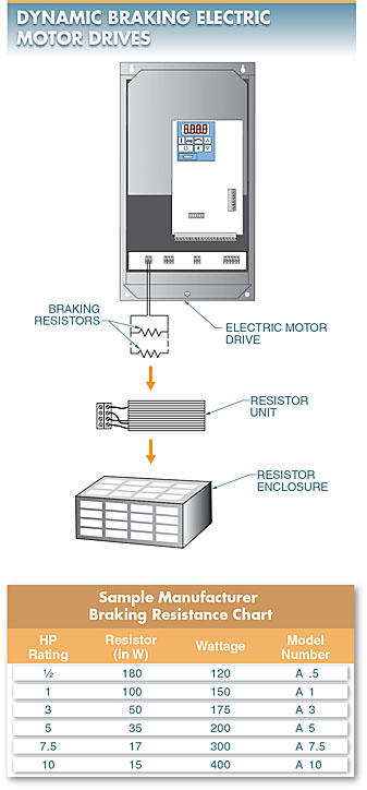
Braking Resistor for DC Motor
When riding an electric motorcycle with frequent stops and starts, the braking resistor also aids in maintaining torque control. The braking resistor is typically chosen according to the drive manufacturer’s braking resistor chart, which specifies the resistor’s size (wattage rating) and resistance (in ohms).
It is imperative that the wattage of the resistor be adequate to dissipate the heat that is applied to the resistor. For the resistor to be effective in turning electrical energy into thermal energy, the resistance value must be low enough to permit current flow without causing excessive current flow. An enclosure, such as a NEMA Type 1 enclosure, can house the braking resistor or resistors.