A relay is a type of electromechanical switch that is used to activate and deactivate electrical circuits. Small loads (less than 15 A) are typically too low a current for a relay to control directly, but this does depend on the design.
Machine tool control, industrial assembly lines, and commercial appliances have all relied on electromechanical relays for years. Contactors and motor starters use relays to switch the current to the starting coil, as do heating elements, pilot lights, audible alarms, and some small motors (less than 1/8, HP).
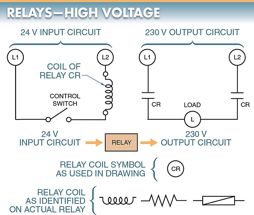
With only a small amount of power, a relay can switch much higher voltages. For an example of this, please refer to Figure 1. When 24 V is applied to the relay coils, the contacts may make and break, regulating the flow of 230 V, for instance. Given that relay coils only need a small amount of current or voltage to switch, but can energize much larger currents or voltages, the relay here functions as an amplifier of the control circuit’s input.
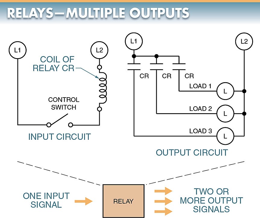
By allowing a single input to activate multiple output circuits, electromechanical relays can also have an amplifying effect. In this case, please refer to Figure 2. Because some mechanical relays allow for the control of eight or more sets of contacts via a single input, this may be interpreted as an amplification of the input.
There are two main categories of relays:
- electromechanical
- solid-state
Electromechanical relays (EMRs) are a type of switching device that uses magnetic forces to close sets of contacts. To switch electrical current, a solid-state relay (SSR) uses only electronic means and has no mechanical contacts.
Types of electromechanical relays
General purpose, machine control, and reed relays are all examples of the types of electromechanical relays used in commercial and industrial settings. The primary distinctions between the many varieties of electromechanical relays are in the circuit function they are designed to serve, the price, and the expected lifespan of the device.
General-Purpose Relays
An electromechanical relay is a mechanical switch that is activated by a magnetic coil and can be used for a variety of purposes. For more information, please refer to Figure 3. Standard relays can be either AC or DC powered. Coils for these electromechanical relays open and close contacts at voltages from millivolts to several hundred volts.
The most common coil voltages for relays are 6 V, 12 V, 24 V, 48 V, 115 V, and 230 V. Electromechanical relays that can be used for a variety of purposes and draw as little as 4mA at 5VDC or 22mA at 12VDC are commercially available. Switching options for these relays are plentiful.
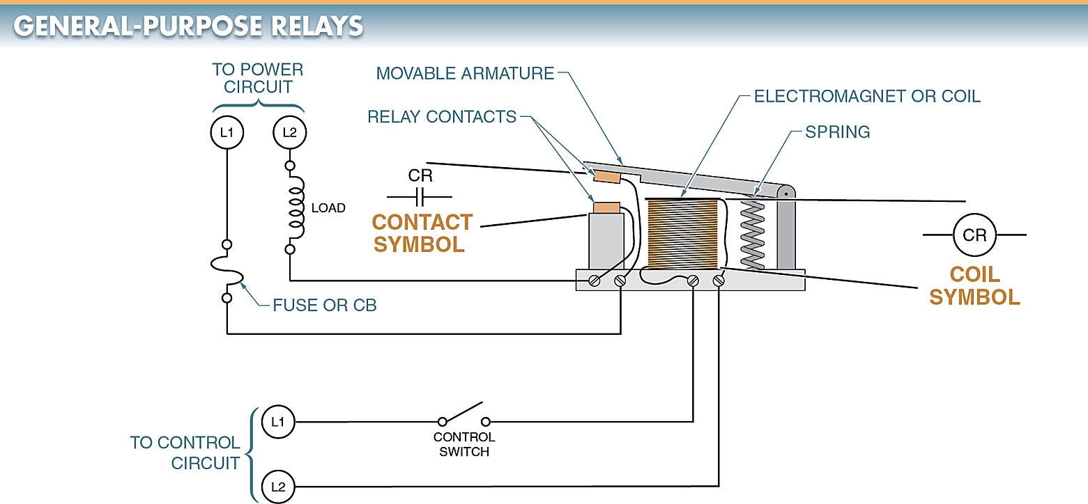
Electromechanical relays with multiple sets of non-replaceable NO and NC contacts (typically rated at 5 A to 15 A) that are triggered by a coil are known as general-purpose relays. Observe the diagram in Figure 4.
If you’re looking to cut down on expenses without sacrificing convenience, a general-purpose relay is the way to go. Since the contact rating for switching DC is less than the contact rating for switching AC, care must be taken when using general-purpose relays to ensure that the appropriate current rating is used. For instance, a contact rated for 15 A AC typically can only handle 8–10 A DC.

Standard electromechanical relays are manufactured with low cost and easy replacement in mind for use in commercial and industrial settings. The general purpose relays that are currently on the market have a plug-in feature that allows for easy maintenance and replacement. They are disposable rather than replaced because of their low cost.
Contacts.
The relay’s contacts are its conducting components, allowing the device to complete or interrupt an electrical circuit. Single-pole, double-throw (SPDT), double-pole, double-throw (DPDT), and triple-pole, double-throw (3PDT) contacts are the most typical types of switches. The pole, throw, and break counts of relay contacts are used to characterize their functionality. Find Figure 5 below.
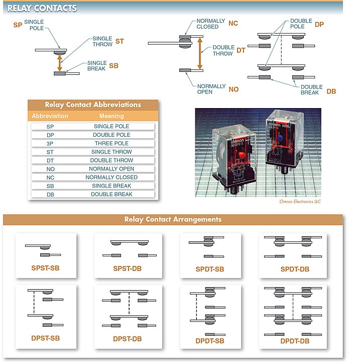
Simply put, the more independent circuits a relay can switch, the more poles it will have. Only one circuit at a time can be powered by a single-pole contact. With a double-pole contact, electricity can flow in two different directions at once.
Both circuits in a double-pole contact are mechanically linked to open or close at the same time, but they are completely isolated from one another electrically. A dashed line from one pole to the other represents the mechanical link. It’s possible to find relays with anywhere from one to twelve contact points.
The number of closed contact configurations between two poles is called a throw. Only one circuit can be controlled by a single-throw contact. Two different circuits can be controlled by a single double-throw contact.
An electrical contact’s break is the total number of its individual openings and closings. A single-break contact, for instance, interrupts current flow only at one point in a circuit.
The electrical connection is severed in two places by a double-break (DB) contact. The only two possible types of contact are the single break and the double break. To easily toggle low-current devices like indicator lights, single-break (SB) contacts are commonly used. Switching high-power devices like solenoids requires double-break contacts.
Tech Tip
There could be more relay contacts in the block than are actually needed. The current flow can be shared between the used and unused relay contacts by connecting them in parallel. By dividing the current flow across multiple sets of contacts, the current flow through any one set is decreased, thereby extending the life of the contacts.
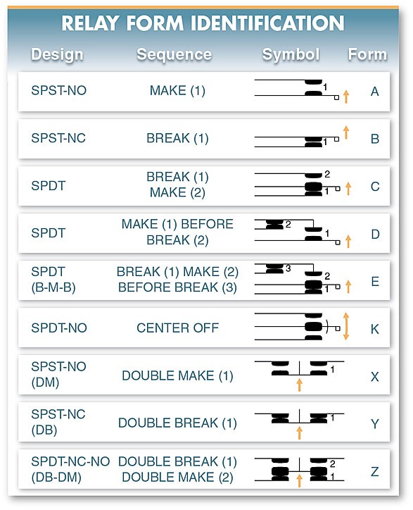
All of the manufacturers of electromechanical relays use a standard code for easy identification. Please refer to Fig. 6. The type of electromechanical relay is indicated by a generic letter in this code.
As an illustration, Form A has a single NO contact that “makes” (closes) when the coil is powered on. In Form B, there is one NC contact that opens up when the coil is activated. When the coil is activated, the one pole in the C form first makes a break in the contact and then makes a new contact. The most common form is C.
In certain electrical applications, arcing can be minimized by knowing the precise order in which each contact operates (makes or breaks). When a contact with a current flowing through it is opened, an arc forms.
Machine Control Relays
An electromechanical relay, a machine control relay has a coil that activates multiple sets of NO and NC replaceable contacts (typically rated at 10 A to 20 A). Because of their central role in electromechanical control circuitry, machine control relays are expected to have a long service life with few breakdowns.
The direct switching of solenoids, contactors, and starters is made possible by machine control electromechanical relays, which see heavy use in machine tools. 7th Figure Electromechanical relays for machine control typically feature time delays, latching contacts, and convertible contacts to allow for a wide range of configurations.
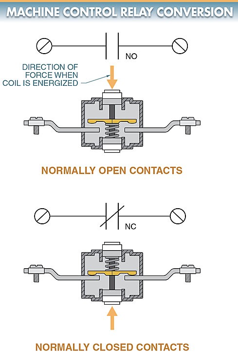
The NO and NC positions of a mechanical contact can be switched with a simple switch. Control relays for machines are also known as heavy-duty or industrial relays.

Each contact in an electromechanical relay used for machine control is a modular component that can be swapped out for a NO or NC contact set. These contacts can switch between the NO and NC configurations as well as the reverse. As shown in Figure 8.
By switching the terminal screws and rotating the unit 180 degrees, you can use it as either a NO or an NC contact. Relays with 1 to 12 contact poles can easily be built using stock components. Additional decks (groups of contacts) may be stacked onto the base unit of machine control relays.
It is simple to switch between AC and DC control voltages, and both AC and DC standard ratings are typically available for the control coils used in machine control relays.
There is a wide variety of attachments that can be used with machine control relays. Indicator lights, transient suppression, latching controls, and time controls all fall into this category.
Reed Relays
Reed relays are a type of electromechanical relay that are characterized by their normally open (NO) contacts and their fast switching speed. Figure 9.
Dry nitrogen is injected into the tube during the sealing process to provide a clean environment for the contacts. The contacts are protected from environmental contaminants like dust and humidity as well as gases and odors. Reed electromechanical relay contacts have a long service life.
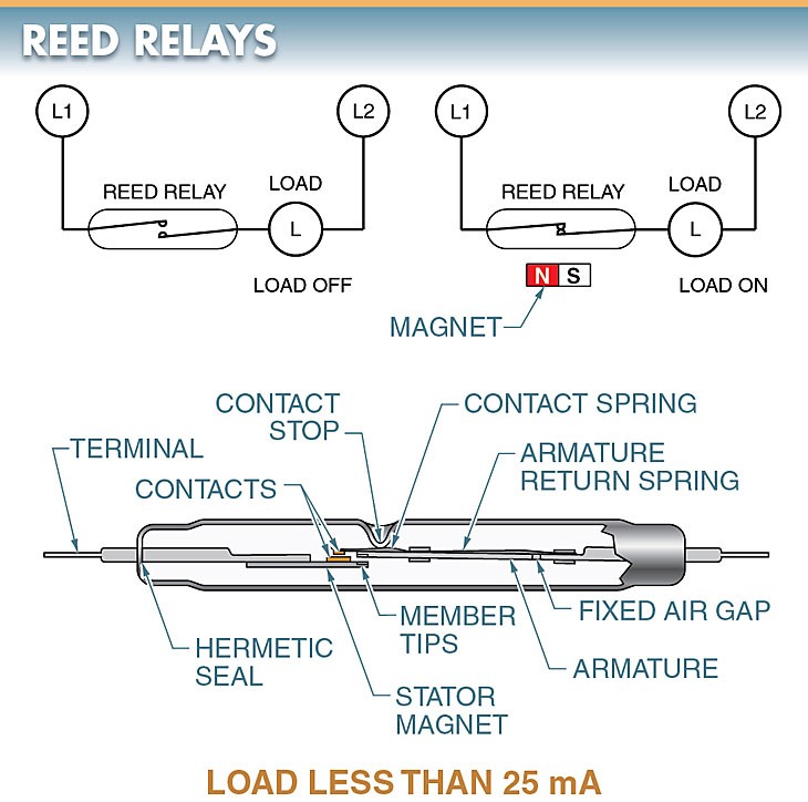
A reed relay is a magnetically activated switch with a very low current rated contact (less than 400 mA). Because of their flexible activation mechanisms, reed relays can be used in circuits where traditional electromechanical relays would not be practical.
A DC electromagnet or a movable external permanent magnet is required to activate a reed relay. In the presence of a magnetic field, the ferromagnetic (easily magnetized) ends of the two reeds will switch places, and the contacts will be drawn together as a result. When the magnetic force is removed, the contacts will automatically open. Since reed relays switch so quickly, they would energize and de-energize on alternate half-cycles of a standard 60 Hz line, making them incompatible with AC electromagnets.
Reed Contacts
Plating the overlapping ends of the contacts with gold, rhodium, silver alloy, or another low-resistance metal can achieve a low and consistent contact resistance. When the contacts are fully closed, their resistance is typically less than 0.1. Reed contacts feature open contact resistances that are in the millions of ohms.
Most reed contacts are not directly capable of switching of industrial solenoids, contactors, and motor starters. The maximum current, voltage, and volt-amps that can be switched by a reed relay are indicated by the relay’s contact ratings. These limits must never be exceeded.
Magnetic fields power Reed relays. False relay operation can be caused by the proximity of unshielded relays (the cheapest type). When the relays can’t be too far apart or when magnetic fields from sources like motors and transformers could cause them to malfunction otherwise, shielded relays are the way to go.
Reed Relay Actuation
The most typical actuator for a reed relay is a permanent magnet. There are a variety of configurations possible for permanent-magnet actuation, depending on the switching need. Proximity motion is one of the most popular setups.
The reed relay in a proximity motion arrangement is activated by a magnetic field that is brought to within a small distance of it. The range at which a given electromechanical relay can be triggered is influenced both by the relay’s sensitivity and the magnet’s strength.
A shorter distance is required to trigger a relay or magnet that is more sensitive or powerful. Proximity motion can be operated in several different ways, including by pivoting, moving in a perpendicular direction, moving in parallel, or moving forward and backward. See Fig. 10. The magnet or the relay is relocated in each technique.
Both the magnet and the relay may be in motion in some uses. The snap action and low wear of the contacts allow for quick operation. What constitutes the optimal approach depends on the nature of the application and the switching mechanisms required.
