PLCs are industrial computers that are ruggedized and designed to handle various tasks, such as controlling robotic devices and assembly lines. They are considered to be the father of the industry’s programmable controllers. The first known PLC was invented in 1968 by Dick Morley, who was the creator of the Modicon 084.
PLCs can be made up of various types of devices, such as small modular units with tens of I/O and a housing that’s integrated with the processor. They can also be used in combination with other systems to control various tasks. They can be designed with various features, such as extended temperature ranges and resistance to electrical noise. Software used to control the machines can be stored in non-volatile or battery-backed memory.
Initially developed for the automotive industry, PLCs were initially designed to replace hard-wire relay logic systems. They have since been widely used in harsh environments due to their high reliability. PLCs are also known to operate in real-time since they have to produce outputs in response to variable input conditions.
Introduction
In the 1960s, businesses started using the first generation of PLCs (programmable logic controllers). Since then, PLCs have become standard equipment for any US factory with a production volume between moderate and massive. It’s spawned an industry worth billions of dollars every year.
It’s not just about making a sale; there are also jobs in setup, coding, and servicing customers in the field. It’s had as much of an effect as the computer and cell phone revolutions of the last few decades. A technician’s ability to control automation in a plant or process relies on their familiarity with PLCs.
This article will introduce the history, components, and programming of programmable logic controllers (PLCs).
Development of the PLC
The automotive sector was the first to benefit from the advent of programmable logic controllers. To control the assembly lines, the factory floor required hundreds of motor control panels with thousands of electromechanical relays, motor starters, pilot devices, and controls.
When there was a need to switch models, the assembly lines would have to be shut down for weeks so that they could be rewired and retooled. Large numbers of hours of work by expert electricians and millwrights were required to complete this. The automaker’s bottom line took a hit from all the maintenance and extra work.
The General Motors Corporation (GM) took the initiative to modernize their production process in the 1960s. In an effort to speed up the process of switching models, the GMC Hydramatic department looked into automating the procedure. It had taken a lot of time and effort to make the switch in models.
Profits would go up while labor costs and downtime went down if the process could be automated. Bedford and Associates (later renamed Modicon) was the firm that GMC contracted to develop a means of speeding up this procedure.
These guidelines were established by the GM engineering team:
- It was necessary to use a solid-state controller.
- The system needed to be as adaptable as a computer.
- The controllers’ capabilities had to allow them to thrive in a manufacturing setting.
- The plant’s electricians should be able to easily update the software.
- The design had to allow for multiple uses.
- The cost had to be lower than that of comparable relay control systems.
- The I/O (Input/Output) ports needed to be swappable without much effort.
- It was necessary to employ a modular layout to facilitate the removal, replacement, and repair of individual subassemblies.
- Data from the manufacturing process must be gathered and transmitted to a centralized database.
- Programming should be done using relay ladder logic, a system already familiar to plant electricians, engineers, and technicians.
The Modicon group investigated the switchover procedure and developed a method to modify the line’s process control logic without requiring a full rewiring of the relays and control panels. Modicon designed a PLC, or programmable logic controller, a small industrial computer that could be placed in each panel.
Each panel received its “programs” (instructions) via radio transmission from a programming device. The PLC’s code directed the operation of all field devices, including motor starters, relays, and pilot devices. Motor control panels served as the hub from which updated software could be sent to the controller and subsequently uploaded. No longer did model swaps necessitate the rewiring of panels and relays, cutting downtime from months to days.
Automaker GM quickly implemented this cutting-edge technology at their assembly plants. This ushered in a brand-new era in process management.
Hundreds of companies around the globe now produce PLCs. The auto industry isn’t the only one benefiting from PLCs. Today, programmable logic controllers (PLCs) can be found in virtually every cutting-edge industry, from manufacturing to transportation to the home heating and air conditioning sector.
They have developed to be the norm for controlling processes in all sectors. Check out this video that provides a quick overview of the history behind the PLC’s creation.
PLC Hardware Components
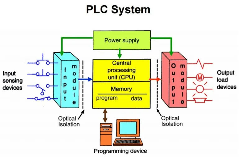
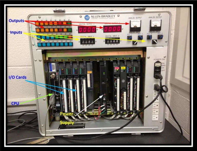
There are several parts that make up a PLC, including the I/O modules, the CPU, the power supply, and the programming device (CPU). To be discussed later, the CPU’s on-board memory also stores the results of logic operations and I/O data tables.
So, let’s back up and define what inputs and outputs are and how they work with a PLC.
PLC Input and output modules (I/O)
The field device dictates whether the inputs and outputs are digital or analog. When a process is running, the PLC can get real-time updates from a field device via an input. A pushbutton switch, pressure sensor, or camera are all examples of possible input field devices.
A process can be monitored by a PLC using any one of hundreds of different inputs. The PLC has no ability to alter the state of the input field device connected to it; it merely reads it periodically to keep track of this information. There are a variety of signal types that can be used for these inputs, including 4-20 milliamps, 24 volts-dc, and 110 volts-ac. A PLC can be configured to accept a wide variety of signals through the use of specialized input cards.
The term “output” refers to a command issued by the central processing unit (CPU) logic to operate a field device. Relays, timers, motor starters, lights, counters, and displays are all examples of devices that could be used in the field. Updated input tables, CPU logic, and a signal to the output field device all contribute to the final output command.
Since the PLC is not directly connected to these inputs and outputs, a failure or electrical short in one could potentially affect the entire controller. The inputs and outputs have both been protected against this possibility. Opto-isolators allow these field devices to communicate with an input/output card.
The signal is converted from its original form by the opto-circuitry isolator’s into a form that the PLC can interpret. Like an input card, an output card is used to do something, but in this case the opposite.
It takes the PLC programming language and transforms it into a signal that can be read by an output field device. Typically, this is done by having an LED (light-emitting diode) glow whenever the input signal is live. A photo diode then converts the light’s intensity into a signal that the PLC can use.
The program monitors the input field devices for changes and updates the input tables and outputs accordingly in real time.
Watch the video down below to learn how input and output modules function.
Programming Device
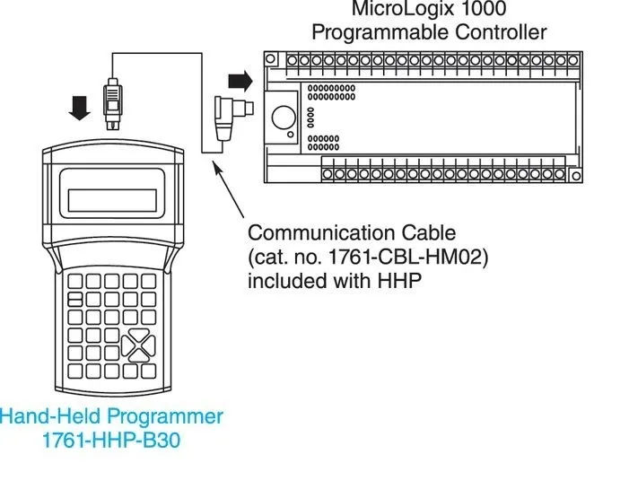
Programming devices allow the developer to create and install software. Devices for programming can also be used to keep an eye on the process’s inputs and outputs in real time and to diagnose problems if the process breaks down. Devices for programming can range widely in type.
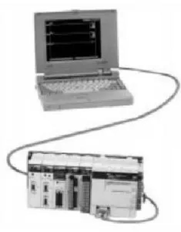
In the beginning, programmers would use handheld devices. Like a scientific calculator, these devices could only show one line of code at a time and were relatively small in size. The personal computer/laptop of today is the most popular device for programming. It is possible to view multiple lines of code at once.
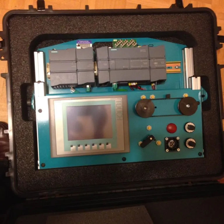
The use of HMIs (Human Machine Interfaces) is on the rise in factories for tracking and fixing production issues. Most are about the size of a laptop screen and are designed to display a live visual of the process. The touch screen allows for interactive modification of process parameters.
A human-machine interface (HMI) or multiple screens can be set up to display a variety of process characteristics.
PLC Power Supply
The Power Supply distributes the various voltages needed by the system’s central processing unit (CPU), field devices, and internal memory.
The standard voltage for the power supply is 110 VAC. Here, the power is filtered to remove any electrical interference and isolated to protect the PLC’s internal components. Then the voltage is lowered or the alternating current is rectified into direct current.
Depending on the use case, the power supply could power the system’s external inputs and outputs.
PLC Central Processing Unit (CPU)
The CPU performs all the logic operations and controls the information flow between the various parts of the system. It serves as the controller and processing center for the PLC. The central processing unit (CPU) provides on-board memory for storing code.
Also, it does calculations, counts, and keeps track of time based on the rules set forth in the program. The CPU receives status updates from field devices externally and then processes those updates by executing the corresponding output function.